
Seat weight measurement system

a weight measurement and seat technology, applied in the field of seat weight measurement system, can solve the problems of varying the accuracy of weight measurement, the occupant of the front passenger seat may be injured, and the device could actually injure the occupants,

Inactive Publication Date: 2005-02-01
KAVLICO CORP
View PDF15 Cites 11 Cited by
  • Summary
  • Abstract
  • Description
  • Claims
  • Application Information

AI Technical Summary

Benefits of technology

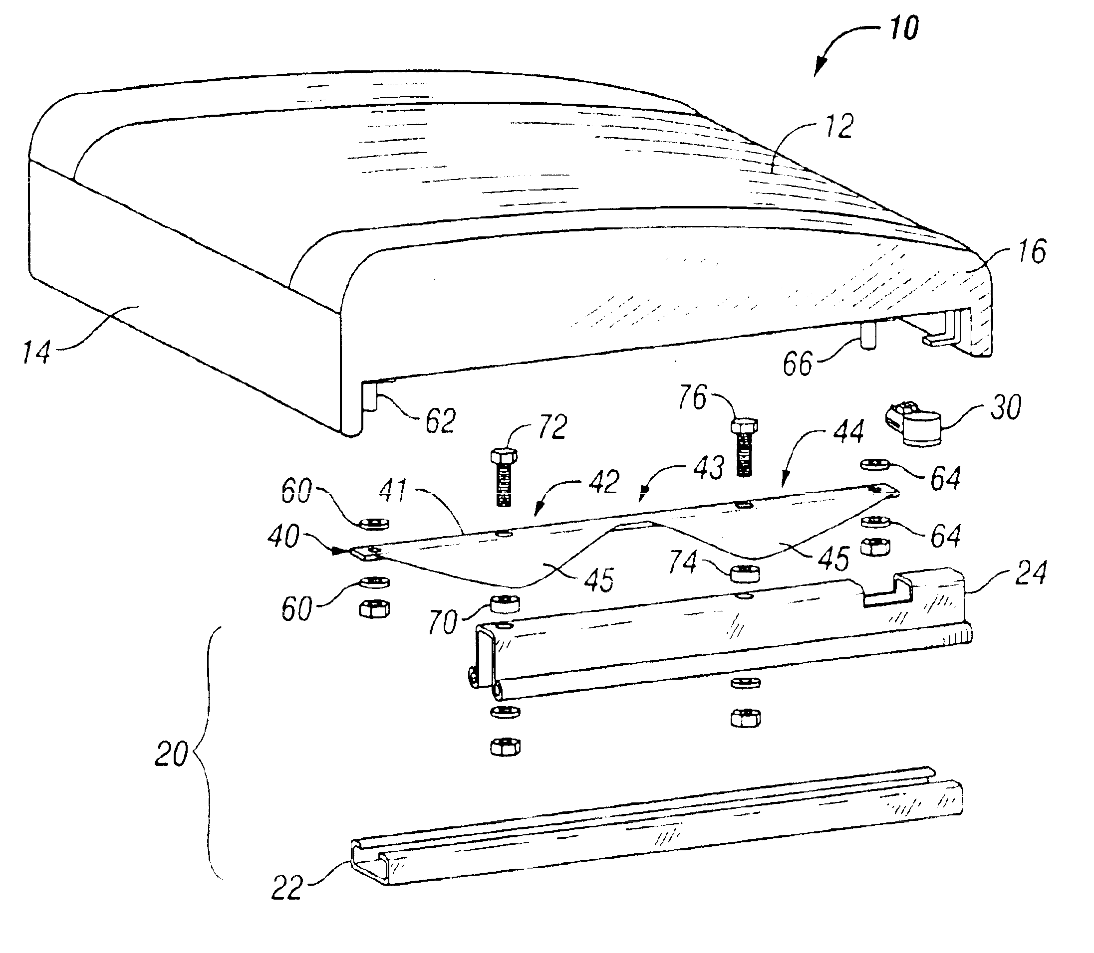
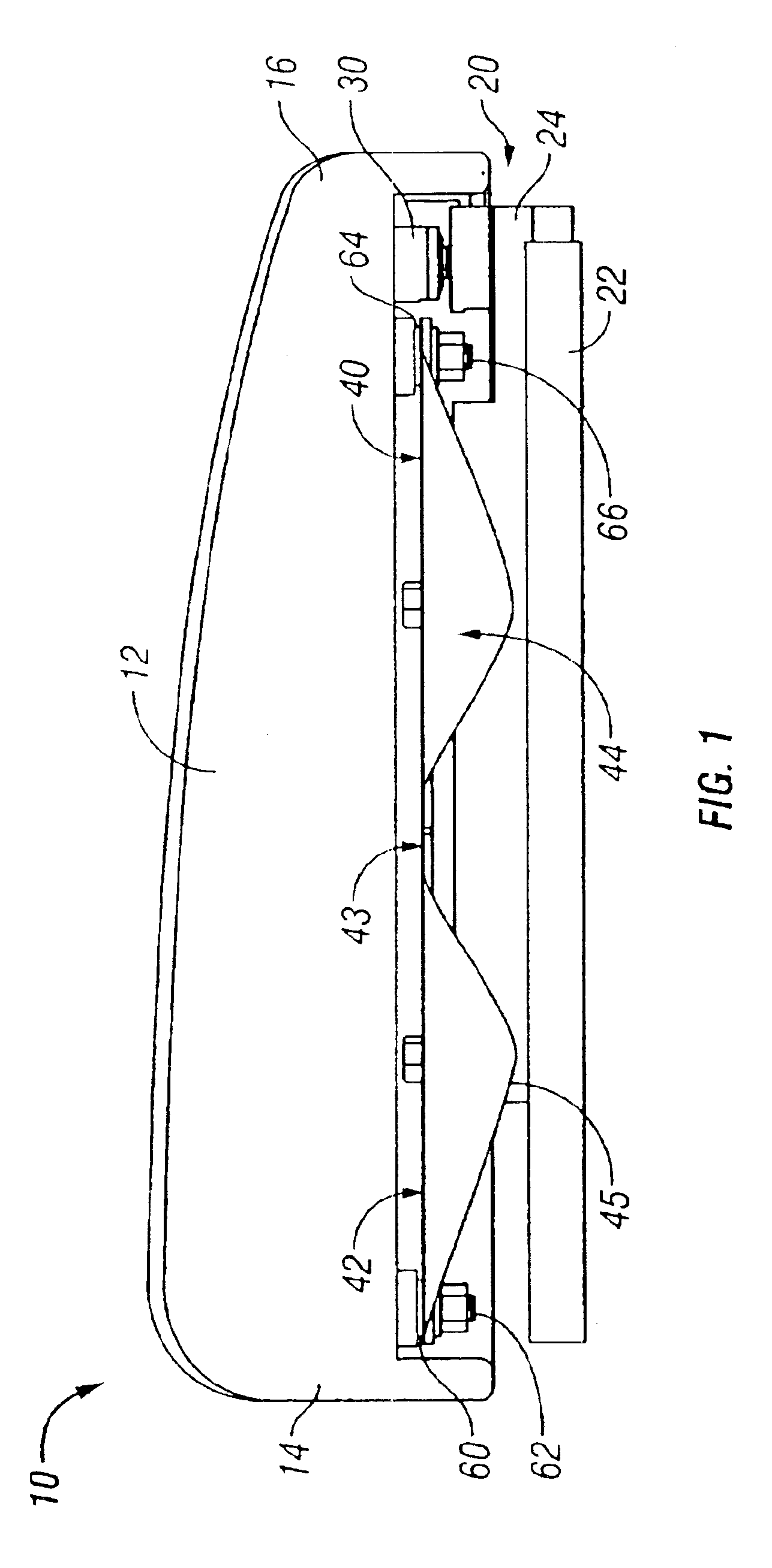
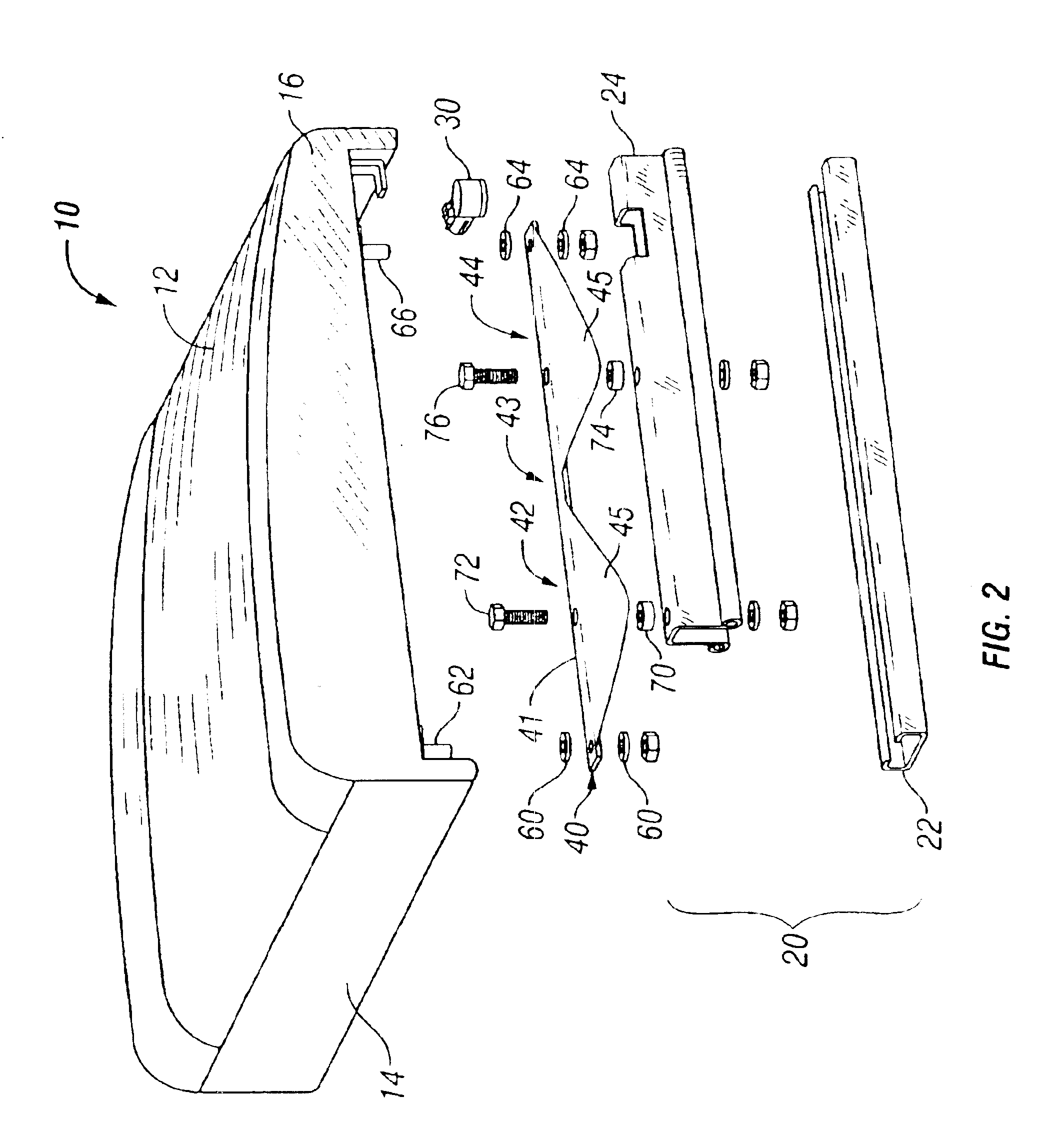
A weight measurement system is disclosed for measuring the weight of an occupant in a vehicle seat. In a preferred embodiment, a sensor is positioned at the close to the fore-and-aft center of gravity of an occupant of a vehicle seat and a load transfer link is used to transfer the weight from the front portion of the vehicle seat to the sensor to be measured. The transfer link is a selectively compliant beam having a first rigid section and a second rigid section connected to each other via a flexible area. The first and second rigid sections preferably include wing portions for increasing the rigidity of the sections. The flexible area is more compliant than the rigid sections. In one embodiment of the invention, the flexible area has a jog to increase the flex. The load transfer link is configured to transition a load placed on the front portion of the link to the rear portion. In a more preferred embodiment of the invention, the load transfer link is made of a high strength, low alloy steel.
In a preferred embodiment of the invention, the load transfer link is connected to the vehicle seat and the rail assembly using bushings and fasteners. In one embodiment of the invention, the front portion of the transfer link is connected to the front portion of the vehicle seat using a bolt and an elastic or plastic bushing. Similarly, the rear portion of the transfer link is connected to the rear portion of the vehicle seat using a bolt and an elastic or plastic bushing. The bushing is compliant, thus allowing the transfer link to move in an angular direction but restricting the translational movement.
Similarly, the transfer link is preferably attached to the mounting bar of the rail assembly by bushings and fasteners. In one embodiment of the invention, the transfer link is attached to the top of the mounting bar, such that the transfer link is seated between the vehicle seat and the mounting bar. In another preferred embodiment of the invention, the transfer link is attached below the mounting bar, such that it is seated between the fixed rail and the mounting bar. In this embodiment, the transfer link is positioned to allow the link to sustain maximum crash forces, thus reducing the risk of failure and the cost of repair.

Problems solved by technology

However, in some situations, these safety devices could actually injure the occupants.
For example, an occupant of the front passenger seat may be injured by the deployment of an airbag if the occupant is a baby or child.
The disadvantage of this known device is that the accuracy of the weight measurement varies with the position of the occupant and the angle of the vehicle seat back.
Furthermore, the puncture-resistance feature of the gel-filled bag is not perfect.
The gel-filled bags often have a sealing problem or get punctured, resulting in gel leakage from the bag.
If the leakage is undetected, the weight measurement result will be inaccurate.
The disadvantage of this system is that each sensor significantly increases the cost of the weight detection system.
Furthermore, depending on the seat configuration and the occupant position, the weight measured by each sensor could vary, resulting in a wide range of force difference between the sensors.
However, the averaging process introduces further errors in the measurement.
Also, the load cells themselves can be damages by crash forces or other overloads.
In the event that the vehicle floor or seat becomes distorted, a wracking load may be placed on the load sensors, and the unequal loading may result in inaccurate weight measurement.

Method used


Image

  • Seat weight measurement system
  • Seat weight measurement system
  • Seat weight measurement system

Examples


Embodiment Construction

A weight measurement system is disclosed for measuring the weight of an occupant in a vehicle seat. In a preferred embodiment, a sensor is positioned at the close to the fore-and-aft center of gravity of an occupant of a vehicle seat and a load transfer link is used to transfer the weight from the front portion of the vehicle seat to the sensor to be measured. The transfer link is a selectively compliant beam having a first rigid section and a second rigid section connected to each other via a flexible area. The first and second rigid sections preferably include wing portions for increasing the rigidity of the sections. The flexible area is more compliant than the rigid sections. In one embodiment of the invention, the flexible area has a jog to increase the flex. The load transfer link is configured to transition a load placed on the front portion of the link to the rear portion. In a more preferred embodiment of the invention, the load transfer link is made of a high strength, low...


PUM


Abstract

A weight measurement system is disclosed for measuring the weight of an occupant in a vehicle seat. In a preferred embodiment, a sensor is positioned at the rear portion of the vehicle seat and a load transfer link is used to transfer the weight from the front portion of the vehicle seat to the rear portion, to be measured by the sensor. The transfer link is a selectively compliant beam having a first rigid section and a second rigid section connected to each other via a flexible area. The first and second rigid sections preferably include wing portions for increasing the rigidity of the sections. The flexible area is more compliant than the rigid sections. The load transfer link is configured to transition a load placed on the front portion of the link to the rear portion. In a more preferred embodiment of the invention, the load transfer link is made of a high strength, low alloy steel.

Description

FIELD OF THE INVENTIONThe present invention relates to a system for accurately detecting the weight of a person seated in a vehicle seat.BACKGROUND OF THE INVENTIONAutomobiles are equipped with restraint systems, such as seat belts, and inflatable restraint systems, such as airbags, to secure safety for passengers. However, in some situations, these safety devices could actually injure the occupants. For example, an occupant of the front passenger seat may be injured by the deployment of an airbag if the occupant is a baby or child. In recent years, there is a trend for controlling the operation of such safety devices according to the weight of a passenger for improved performance of seat belts and airbags. For example, the amount of gas introduced into the airbag, an airbag inflating speed, or a pre-tension of the seat belt are adjusted according to the weight of a passenger. For that purpose, it is desirable to provide a device for measuring the weight of a passenger sitting on a ...

Claims


Application Information

Patent Timeline
Patent Type & Authority Patents(United States)
IPC IPC(8): B60N2/06B60N2/07G01G19/414G01G19/40B60N2/90G01G19/12B60R21/16B60R22/46G01G19/52
CPCB60N2/0705G01G19/4142B60N2/0732B60N2/0715
Inventor CASEY, GARYCROSS, ALAN
Owner KAVLICO CORP
Learn More