Forecasted radar mosaics

Inactive Publication Date: 2005-02-01
DTN LLC
View PDF6 Cites 28 Cited by
  • Summary
  • Abstract
  • Description
  • Claims
  • Application Information

AI Technical Summary

Benefits of technology

The present invention provides a system that extends these techniques of the prior art to build a radar reflectivity forecast mosaic from a collection of radar sites. The radar data from multiple radar sites is processed to create movement information for all of the precipitation areas. The m

Problems solved by technology

This occurs particularly in thunderstorms, where the accuracy of predicting the motion of the storm front is poor.
Thus, it is possible that a single site's radar reflectivity information ma

Method used


Image

  • Forecasted radar mosaics
  • Forecasted radar mosaics
  • Forecasted radar mosaics

Examples


Embodiment Construction

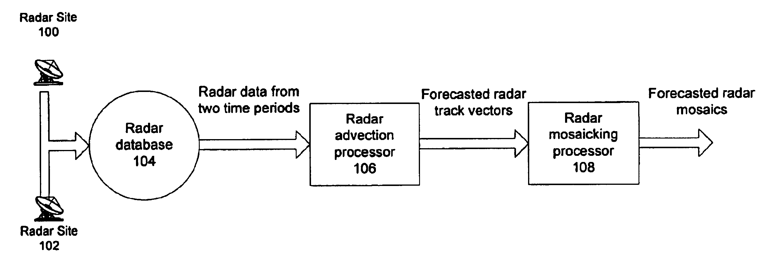
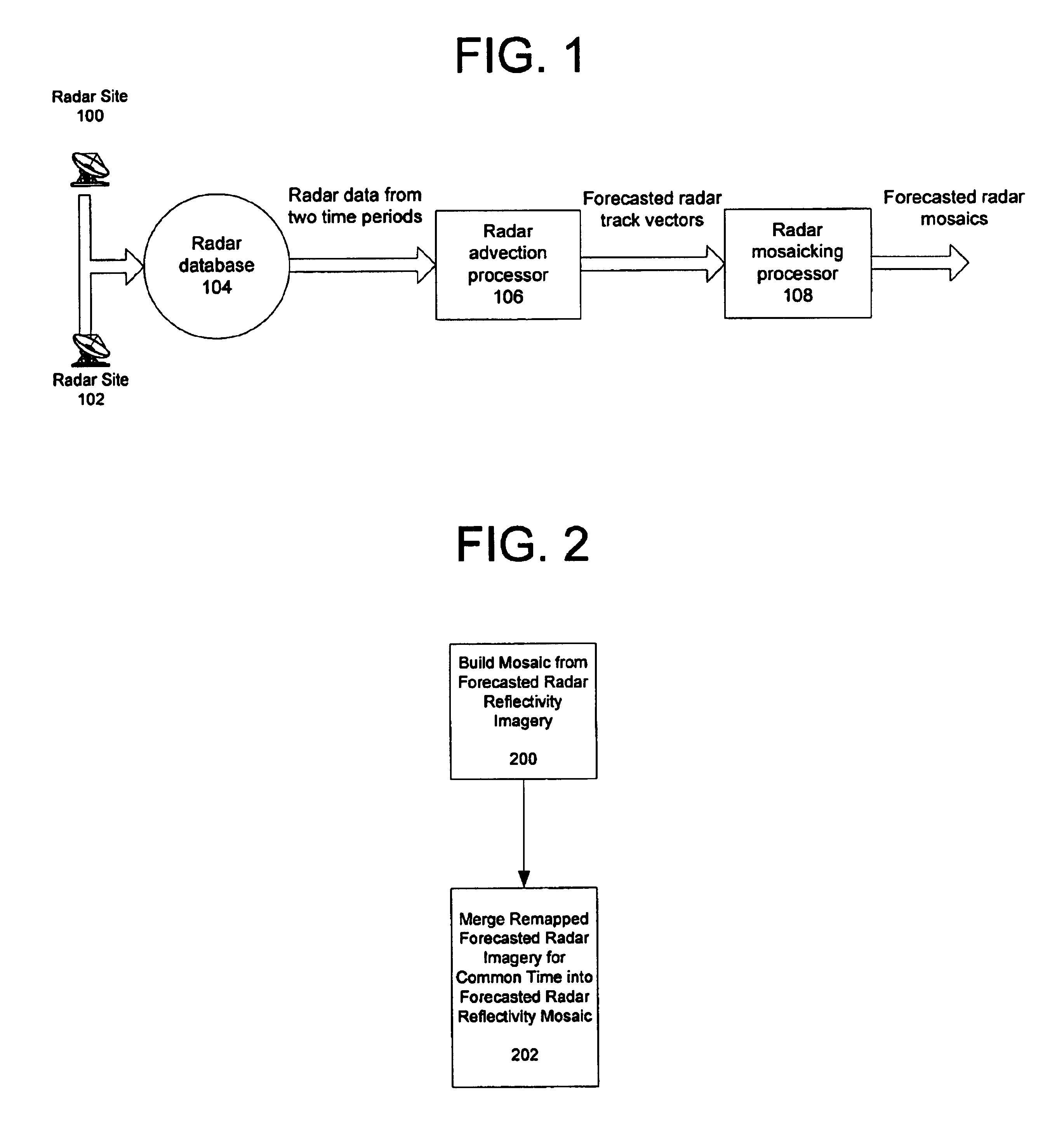
In accordance with the present invention, radar reflectivity information from multiple sites is used to create a forecasted radar mosaic. This advantageously provides a more accurate forecasted radar picture that is a better predictor of future weather than conventional systems that utilize a single radar site's data to generate a forecasted radar picture. Referring now to FIG. 1, there is an overview of the system of the present invention. Radar sites 100 and 102 periodically obtain radar reflectivity information regarding a particular location under observation. The radar information from the sites 100 and 102 is forwarded to a radar processing facility and stored in a database 104. The database 104 stores observed radar reflectivity information for at least two time periods.

Typically, radar images are produced by radar sites at a rate of approximately 10 images per hour. This frequency is inadequate to measure rain cell movement during fast moving storms because of the gaps betwe...


PUM


Abstract

A system and method to build a radar reflectivity forecast mosaic from a collection of radar sites. The radar data from multiple radar sites is processed to create movement information for all of the precipitation areas. The movement information and precipitation areas are then mosaicked in a common geographical framework to create forecasted radar reflectivity mosaics. By using the reflectivity information and movement information from multiple radars, a wider scale, more coherent radar forecast can be generated.

Description

FIELD OF THE INVENTIONThe present invention is directed to weather forecasting and, in particular, a method of producing a composite forecasted radar mosaic.BACKGROUND OF THE INVENTIONWeather forecasting of storms and other meteorological events is extremely important to aviation, emergency response agencies, utilities and other entities that provide for public safety and welfare. Techniques have been devised to create short term forecasts of radar reflectivity by processing data from a single radar site. Such techniques track clusters or cells to predict storm motion by correlating cells in two or more successive images to determine speed and direction of a storm front. This movement information is then used to project where the precipitation areas are likely to be located in the next thirty to sixty minutes which is represented in the form of forecasted radar reflectivity images.Often, however, the direction of cells is different than the direction of the storm front. This occurs ...

Claims


Application Information

Patent Timeline
IPC IPC(8): G01S13/95G01S13/00G01S13/72G01S7/00
CPCG01S13/951G01S13/723G01S7/003Y02A90/10
Inventor DESROCHERS, GEORGE RENEBAYER, PAUL JOSEPHRODER, BRENDA JOYCEKLEIST, MICHAEL ROBERT
Owner DTN LLC
Why Eureka
Try Eureka