
Systems and methods for MPEG subsample decoding

a subsample and subsample technology, applied in the field of digital video, can solve the problems of wasting memory resources and computational resources, unable to support any and all desired output resolutions simultaneously in a broadcast environment, and limited terrestrial channel allocations

Inactive Publication Date: 2005-02-01
MICROSOFT TECH LICENSING LLC
View PDF4 Cites 106 Cited by
  • Summary
  • Abstract
  • Description
  • Claims
  • Application Information

AI Technical Summary

Benefits of technology

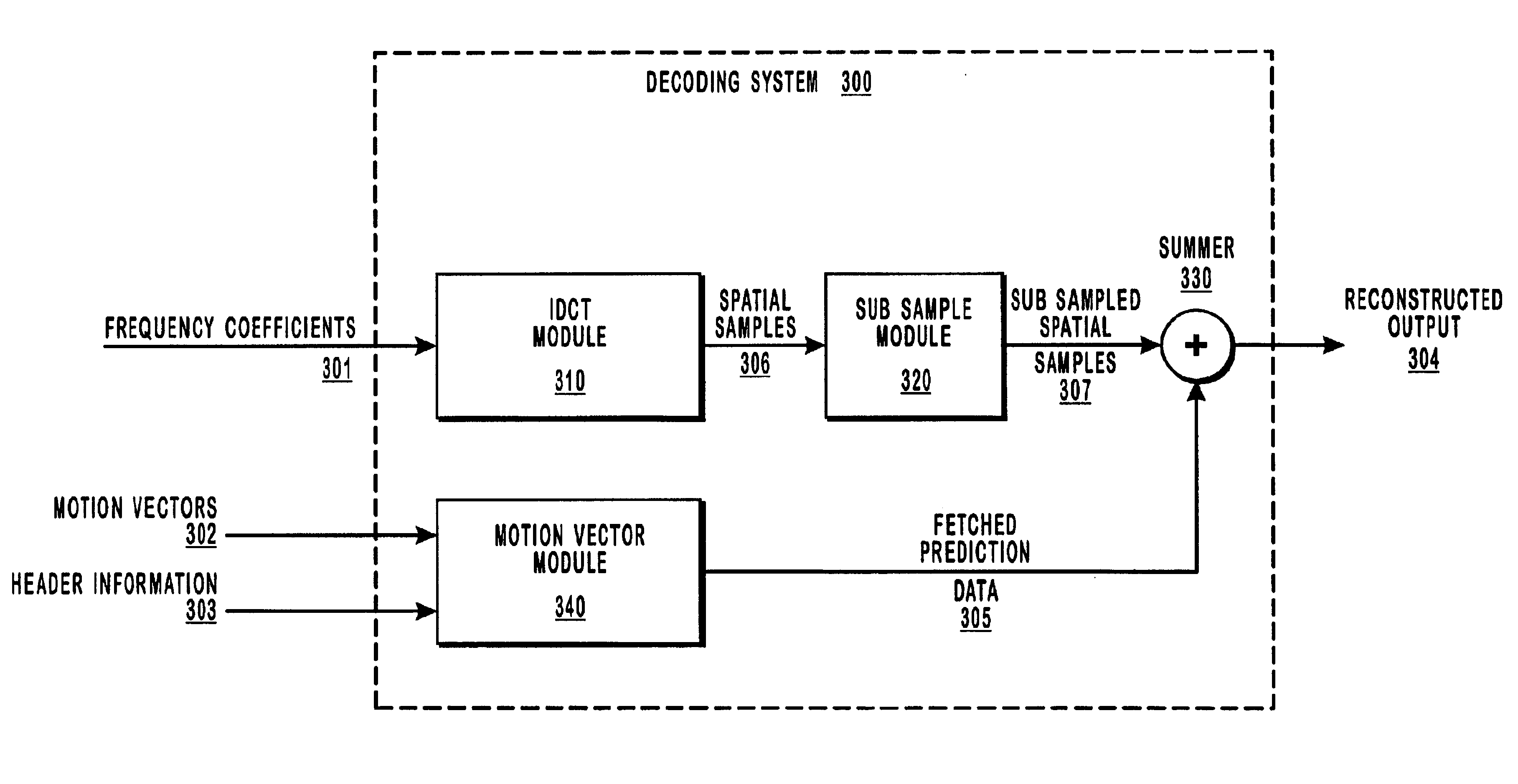
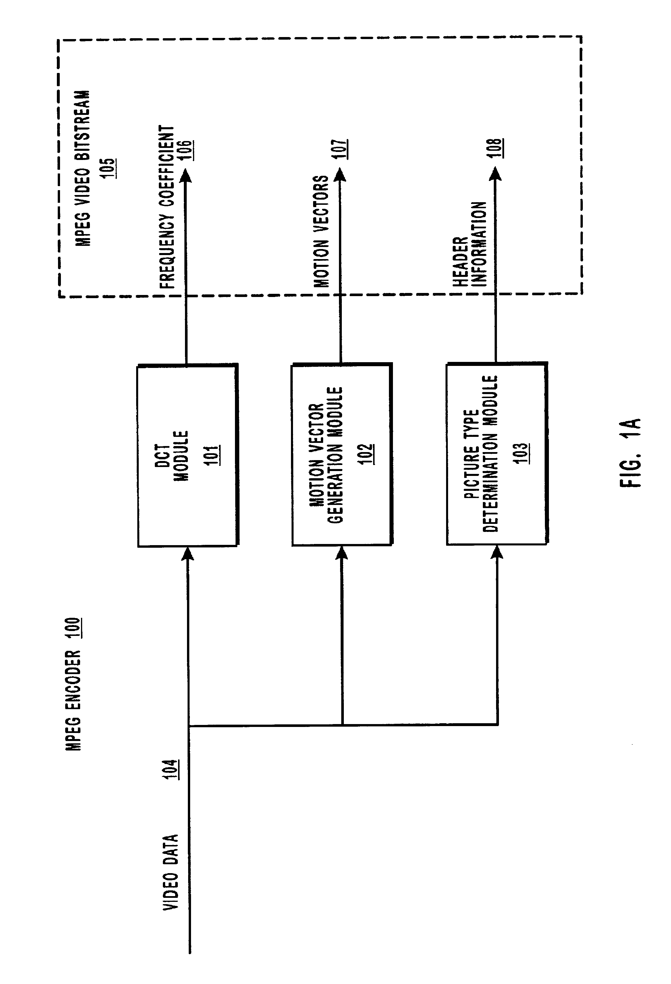
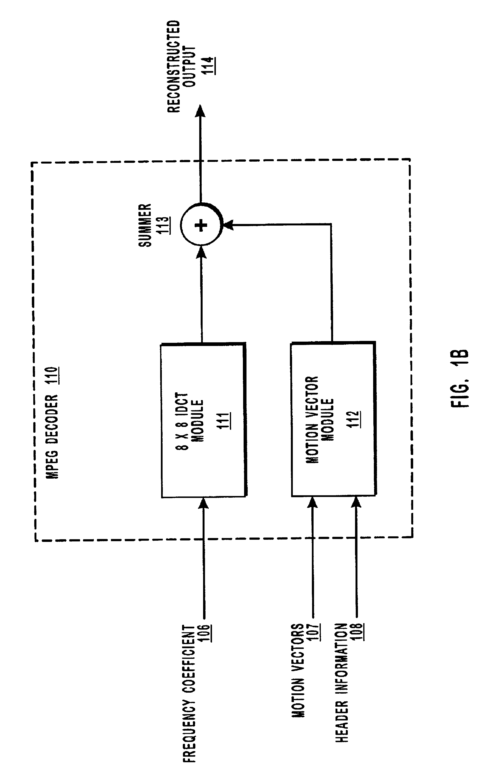
The principles of the present invention provide for efficiently subsampling video data for display at a lower resolution than what the video data was originally encoded for. MPEG video bit streams are decoded by dequantizing frequency coefficients and passing them through an IDCT module to convert the coefficients back into the spatial domain representations, passing header information and motion vectors through a motion vector prediction module to fetch predictions from previously decoded images, and then summing the spatial domain representations and the fetched prediction data. The present invention performs decimation on the output of the IDCT module before it is summed with the results of the prediction module. Using this method, predictive and bi-directionally predictive frames do not significantly degrade beyond any initial blurring or softening associated with corresponding reference frames, particularly where the video frames represent relatively static images or constant pans.

Problems solved by technology

However, current terrestrial channel allocations are limited to 6 Mhz.
However, decoding an MPEG video bit stream having full HDTV formatting and then resampling to a lower resolution wastes memory resources and computational resources, since the receiving device cannot display the full resolution of the image.
However, they are all limited in that they cannot support any and all desired output resolutions simultaneously in a broadcast environment, since the processing is performed prior to transmission, rather than at the decoding or display devices where the images are to be displayed.
Also, most of these methods would involve non-standard profiles of MPEG video compression.
This method is hindered by the fact that the output subsampling may require some extra buffering in order to allowing vertical filtering.
Also, for relatively static scenes or constant pans, the error terms coming from the IDCT are nearly zero, which results in effectively the same image data being upsampled and downsampled many generations.
This generational loss progressively degrades the image quality until an I-frame is decoded, in which case the image is refreshed.
This results in a “beating” effect that is most noticeable and irritating to the viewer.
However, simply ignoring the high frequency IDCT components can produce some significant artifacts at the boundaries of blocks and macroblocks in the decoded image (otherwise know as “block” artifacts).
These artifacts in turn can significantly affect subsequent images that use the previous ones as references.
Also, the 4×4 IDCT is slightly different from the 8×8 IDCT and for some hardware implementations is not easily changed.

Method used


Image

  • Systems and methods for MPEG subsample decoding
  • Systems and methods for MPEG subsample decoding
  • Systems and methods for MPEG subsample decoding

Examples


Embodiment Construction

The present invention extends to both methods and systems for subsampling and displaying video images that have been encoded using an HDTV format and in an MPEG video bit stream on a device of lower resolution, such as standard television, or on a picture-in-picture display. The embodiments of the present invention may comprise a special purpose or general-purpose processing device or computer including various computer hardware components, as discussed in greater detail below. The embodiments may further comprise multiple computers linked in a networked environment. Set top boxes that enhance the capabilities of conventional televisions represent an example of a special purpose computer.

Embodiments within the scope of the present invention also include computer-readable media for carrying or having computer-executable instructions or data structures stored thereon. Such computer-readable media can be any available media that can be accessed by a general purpose or special purpose c...


PUM


Abstract

Decimating MPEG or other video data by subsampling the output of an inverse discrete cosine transform (IDCT) module. The decimation process is useful for reducing the volume of data that must be processed to display images on a display device, particularly when the volume of video data received at the decoder is greater than the amount needed to take advantage of the resolution of the display device. For example, high definition television data can be decimated for display on a standard television display device or in a picture-in-picture window, thereby reducing the amount of processing resources needed at the decoder and reducing the size of the frame buffers. Subsampling the output of the IDCT module reduces the volume of data and, for relatively static or constant pans, there is not a significant compounded loss of image quality as successive frames are decoded.

Description

BACKGROUND OF THE INVENTION1. The Field of the InventionThe present invention relates to the field of digital video. More specifically, the present invention relates to reducing the memory bandwidth and memory footprint needed to decode and display MPEG video streams.2. The Related ArtHigh Definition Television (“HDTV”) is a type of television that provides much better resolution than televisions based on National Television Systems Committee (“NTSC”) standard. Although there are a number of competing HDTV standards, all standards support a wider screen than NTSC and roughly twice the resolution. Sending uncompressed analog HDTV data requires a bandwidth of about 18 Mhz. However, current terrestrial channel allocations are limited to 6 Mhz. As a result, HDTV video frames are digitized and then compressed before they are transmitted and then decompressed when they reach a receiving device, such as an HDTV television.One widely used compression method is based on the Moving Pictures E...

Claims


Application Information

Patent Timeline
Patent Type & Authority Patents(United States)
IPC IPC(8): G06T3/40G06T9/00H04N7/36H04N7/26H04N7/46
CPCG06T3/4084H04N19/51H04N19/48H04N19/59H04N19/428H04N19/90H04N19/467
Inventor TARDIF, JOHN A.
Owner MICROSOFT TECH LICENSING LLC
Learn More