Method and apparatus for determining calibration options in a motion control system

a technology of motion control system and calibration option, which is applied in the direction of electric controllers, program control, instruments, etc., can solve the problem of limited range of motion of commercially available ball bars, and achieve the effect of reducing the range of motion of commercially available balls

Inactive Publication Date: 2005-02-01
SIEMENS ENERGY & AUTOMATION INC
View PDF40 Cites 67 Cited by
  • Summary
  • Abstract
  • Description
  • Claims
  • Application Information

AI Technical Summary

Problems solved by technology

Typically, the range of motion of a commercially available ballbar is limited to just a few millimeters.

Method used


Image

  • Method and apparatus for determining calibration options in a motion control system
  • Method and apparatus for determining calibration options in a motion control system
  • Method and apparatus for determining calibration options in a motion control system

Examples


Embodiment Construction

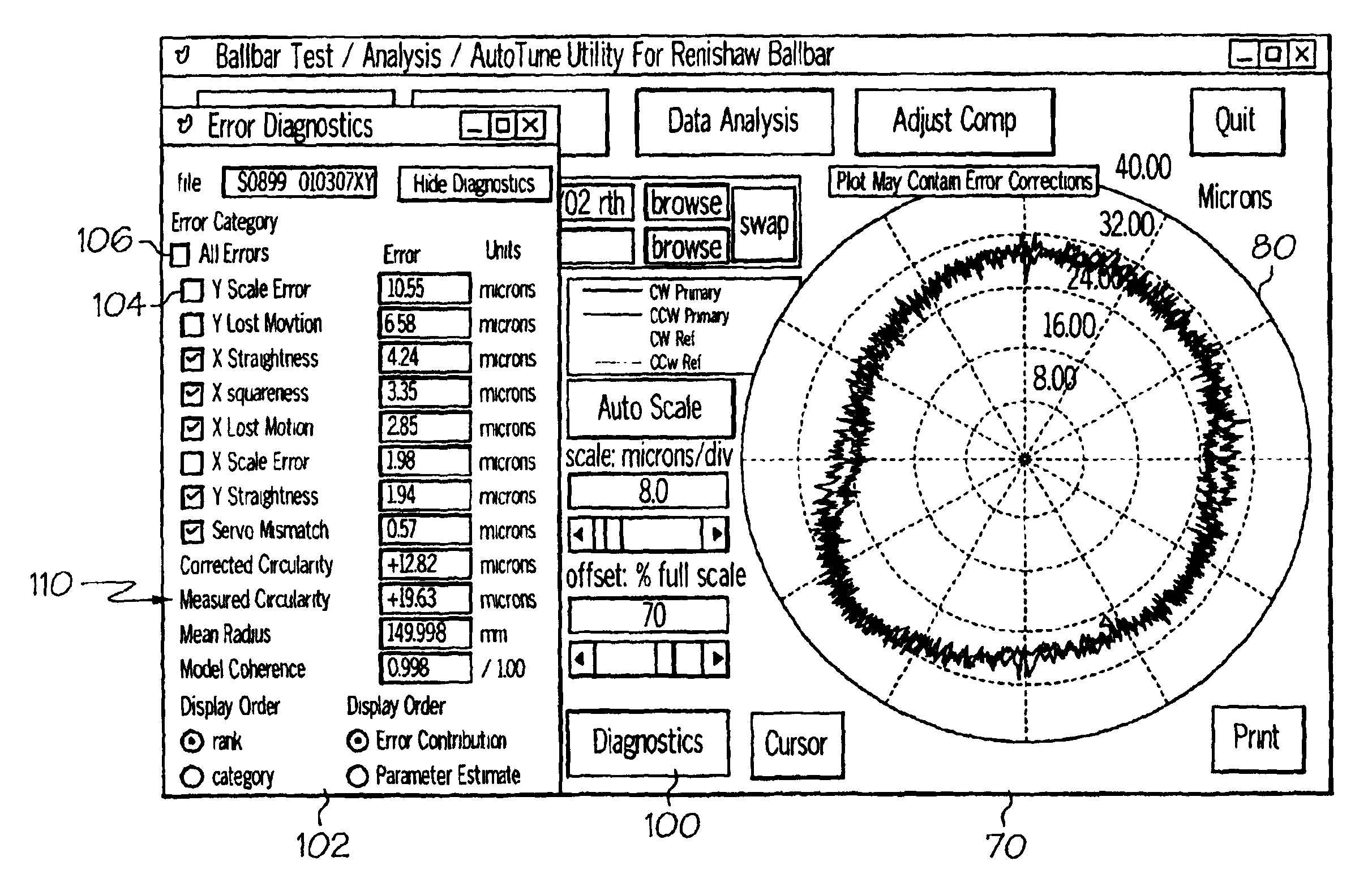
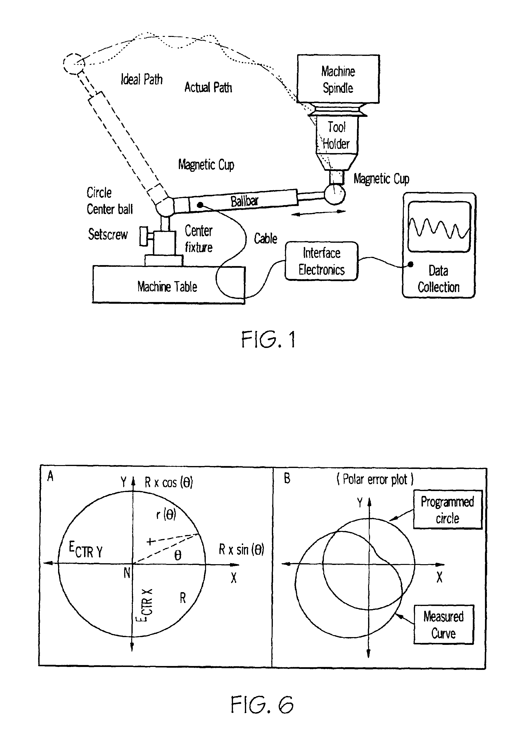
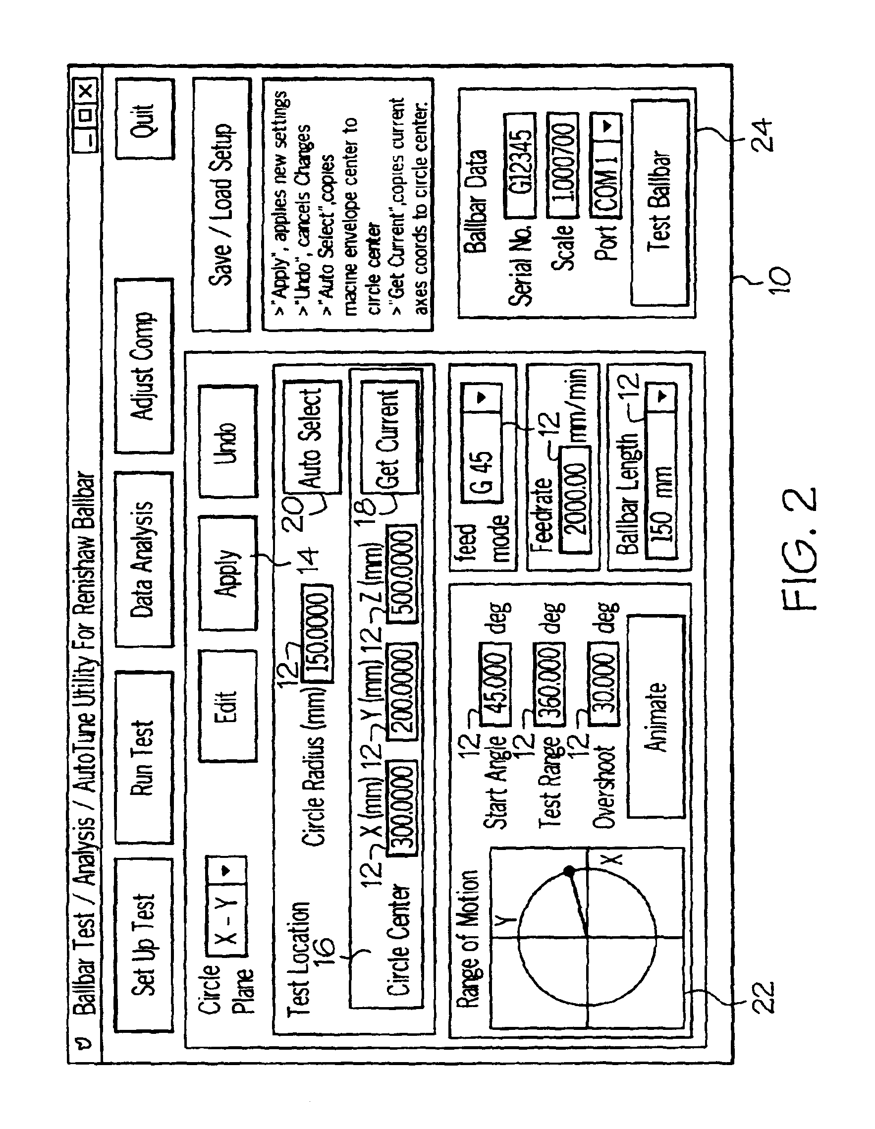
In general, the present invention relates to a motion control system capable of tuning compensation parameters. For purposes of illustration, exemplary embodiments discussed primarily herein relate to test software that runs on the control of a machine tool and, in one embodiment, to such software that allows a machine tool control to self-calibrate its parametric compensation based on measurements from an instrument called a telescoping ballbar. Moreover, in one embodiment, disclosed exemplary software provides the capability to: 1) specify test conditions; 2) automatically create the motion for measurements related to the test condition; 3) initiate the motion; 4) collect the data; 5) analyze the data; and 6) update the compensation of the control based on the data.

Further exemplary embodiments can, for example, be used to:1. Validate the appropriateness of test setup data.2. Validate the integrity of collected data.3. Aid a user in fixture setup by providing prompts of what to do...


PUM


Abstract

In one embodiment, a method of and apparatus for determining calibration options in a motion control system is provided. The method includes the steps of measuring error in a commanded motion, modeling the error, identifying sources of the error; and predicting a degree to which applying compensation for one of the sources of the error might affect the error.

Description

TECHNICAL FIELDThe present invention relates generally to motion control systems, and more particularly, to a method and system for tuning compensation parameters.BACKGROUND OF THE INVENTIONThe performance of a motion control system is of primary importance. In particular, a control system should be stable, result in acceptable responses to input commands, result in a minimum steady-state error for input commands, and be able to eliminate the effect of undesirable disturbances. Often-times, for optimum performance, adjustments are made to a control system. The alteration or adjustment of a control system in order to provide a desired performance is often referred to as compensation (i.e., compensation is the adjustment of a system in order to make up for deficiencies or inadequacies).In some cases, an additional component (e.g., a compensator) is included within a motion control system to equalize or compensate for such deficiencies / inadequacies. For example, such compensators can b...

Claims


Application Information

Patent Timeline
Patent Type & Authority Patents(United States)
IPC IPC(8): G05B19/404G05B11/42G05B13/04G05B11/28G05B11/01
CPCG05B11/28G05B11/42G05B13/042G05B19/404G05B2219/50139G05B2219/39015G05B2219/49181
Inventor YUTKOWITZ, STEPHEN J.
Owner SIEMENS ENERGY & AUTOMATION INC
Why Eureka
Try Eureka