Apparatus and method for controlling intake air amount of internal combustion engine
a technology of intake air and intake air, which is applied in the direction of combustion engines, valve arrangements, machines/engines, etc., can solve the problems of inability to apply engine pressure, inability to generate, and inability to ensure torque linearity, etc., and achieve the effect of higher accuracy
- Summary
- Abstract
- Description
- Claims
- Application Information
AI Technical Summary
Benefits of technology
Problems solved by technology
Method used
Image
Examples
first embodiment
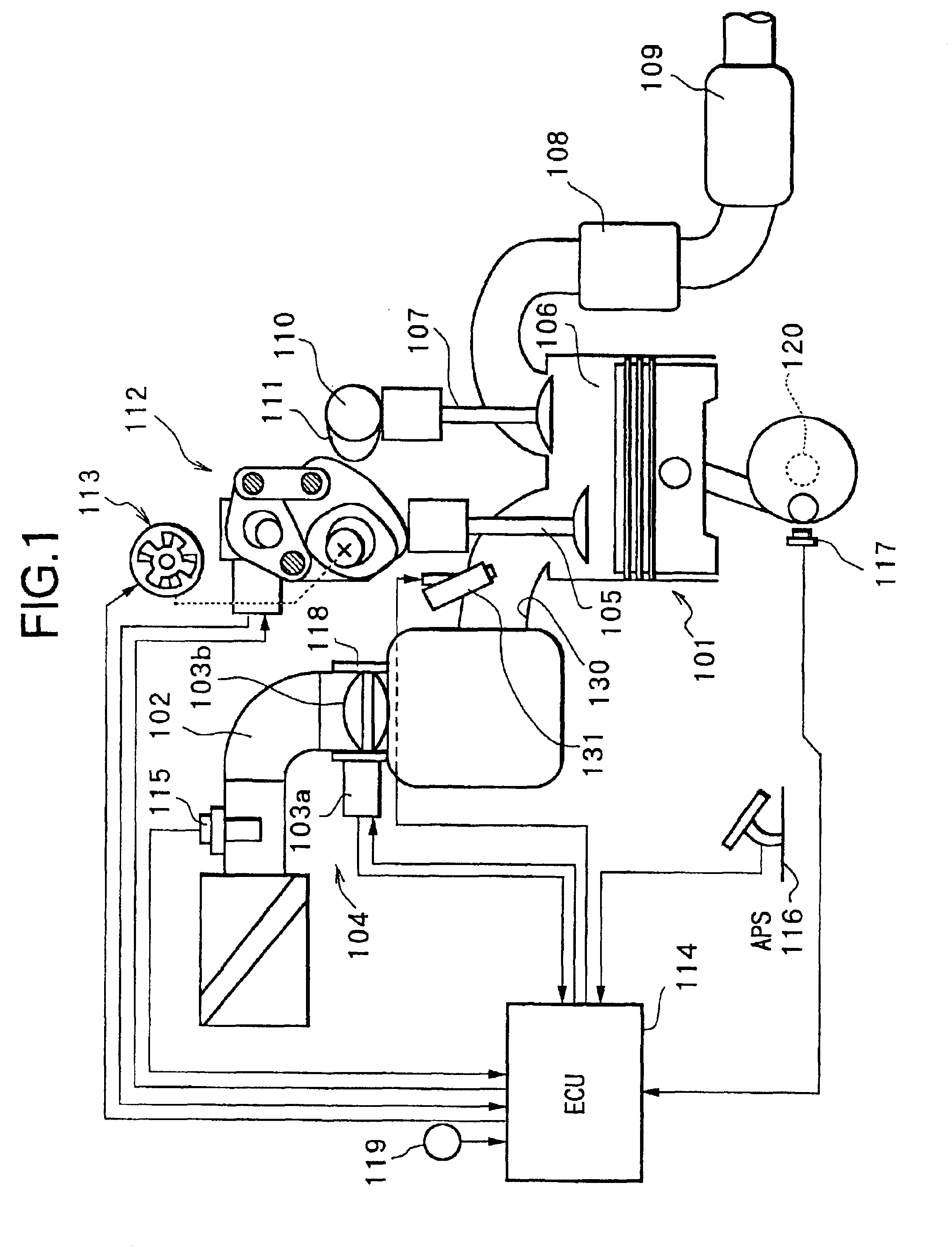
[0086]In the constitution as mentioned in the above, there will be described in detail an intake air amount control executed by control unit (C / U) 114, that is a control on electronically controlled throttle 104, variable valve mechanism (VEL) 112 and variable valve timing mechanism (VTC) 113 (a first embodiment).
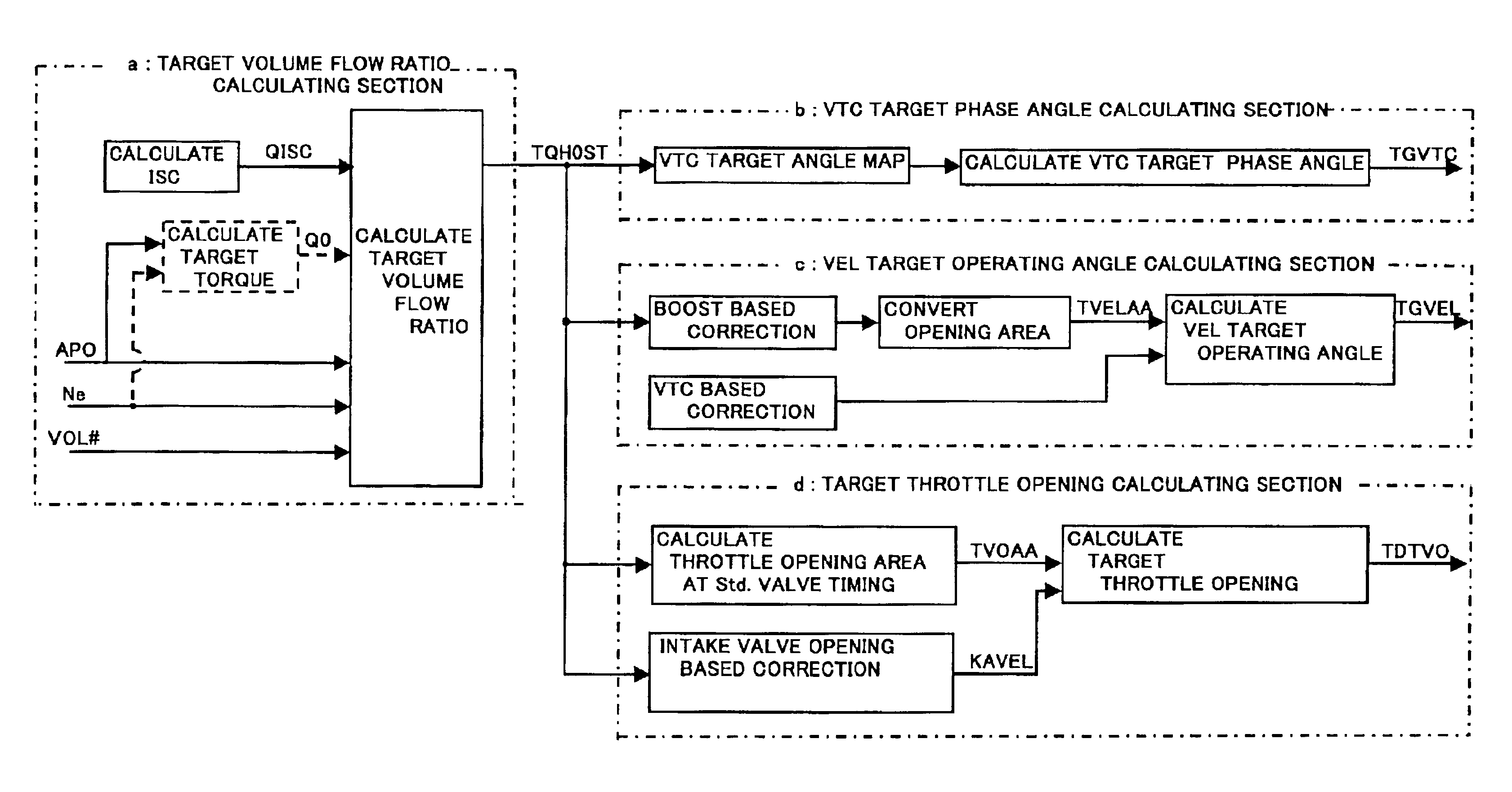
[0087]As shown in FIG. 12, control unit (C / U) 114 includes a target volume flow ratio calculating section “a”, a VTC target operating angle calculating section “b”, a VEL target operating angle calculating section “c” and a target throttle opening calculating section “d”.
[0088](a) Calculation of Target Volume Flow Ratio TQH0ST
[0089]The target volume flow ratio calculating section “a” calculates a target volume flow ratio TQH0ST equivalent to a target torque as follows.
[0090]Firstly, a requested air amount (a requested engine air amount) Q0 corresponding to accelerator opening APO and engine rotation speed Ne (or, that so as to obtain a target torque set based on accelerator...
second embodiment
[0178]Next, other embodiment (second embodiment) of intake air amount control to be executed by control unit (C / U) 114 will be described with reference to block diagrams of FIG. 21 to FIG. 24.
[0179]In this embodiment, intake valve 105 is controlled to a target valve operating characteristic. While, in a total opening area (an integrated value of opening areas) obtained based on the target valve operating characteristic, since the opening area during valve overlap period is an ineffective portion where air is not newly sucked, the total opening area is corrected with a correction value according to the valve overlap to be made a total opening area (effective opening area) where air is newly sucked, so that the total opening area (effective opening area) indicative of intake air amount actually controlled by intake valve is compared with the target intake air amount to set a target opening of throttle valve 103b.
[0180]In FIG. 21, a target volume flow ratio calculating section 301 cal...
PUM
 Abstract
Description
Claims
Application Information
 - R&D
- Intellectual Property
- Life Sciences
- Materials
- Tech Scout
- Unparalleled Data Quality
- Higher Quality Content
- 60% Fewer Hallucinations
Browse by: Latest US Patents, China's latest patents, Technical Efficacy Thesaurus, Application Domain, Technology Topic, Popular Technical Reports.
© 2025 PatSnap. All rights reserved.Legal|Privacy policy|Modern Slavery Act Transparency Statement|Sitemap|About US| Contact US: help@patsnap.com


