Tube fitting for medium pressure applications

Inactive Publication Date: 2005-02-08
PARKER INTANGIBLES LLC
View PDF35 Cites 67 Cited by
  • Summary
  • Abstract
  • Description
  • Claims
  • Application Information

AI Technical Summary

Benefits of technology

In an illustrated embodiment of the fitting construction of the present invention, the body is configured as having a seating surface which extends substantially the full length of the of the front ferrule, and which may terminate to define a radial stop having a diametric extent which is less than that of the inner sur

Problems solved by technology

Although fittings are currently available which are specified for use in “medium” pressure applications, these fittings generally are of a “non-standard” variety in requiring additional components or makeup steps.
In this regard, however, fittings of a conventional design which are currently used with softer, annealed tubing used in instrumentati

Method used


Image

  • Tube fitting for medium pressure applications
  • Tube fitting for medium pressure applications
  • Tube fitting for medium pressure applications

Examples


Embodiment Construction

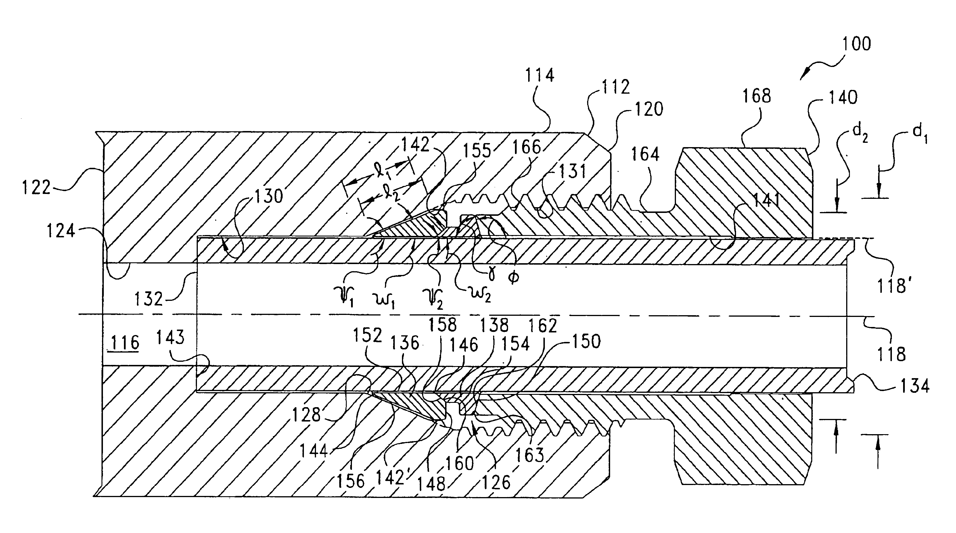
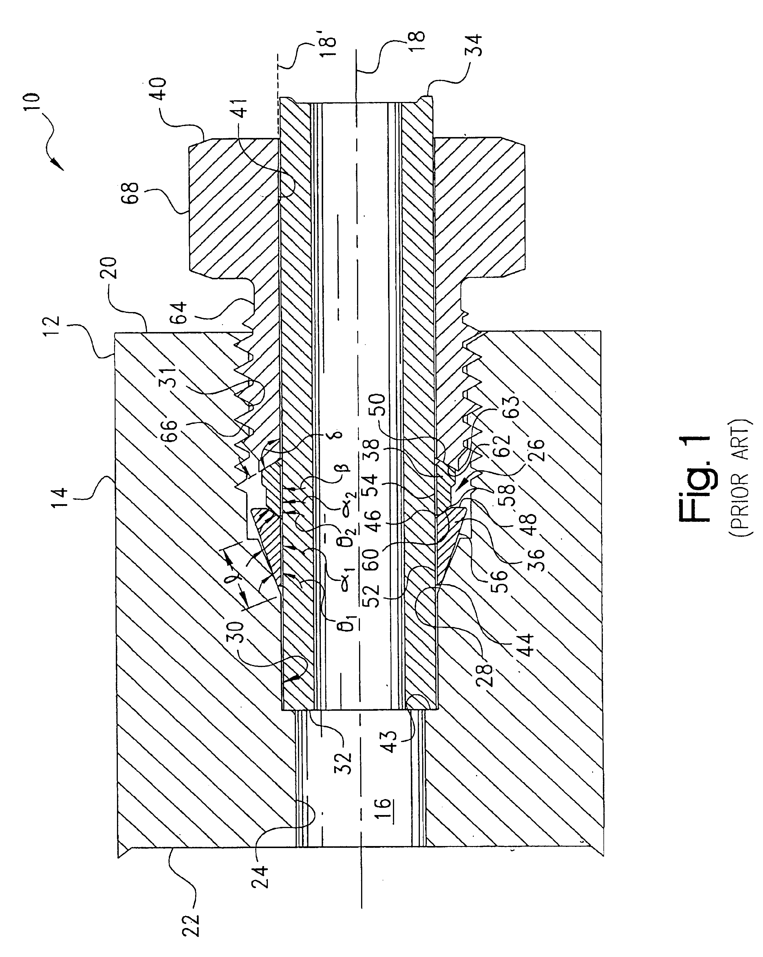
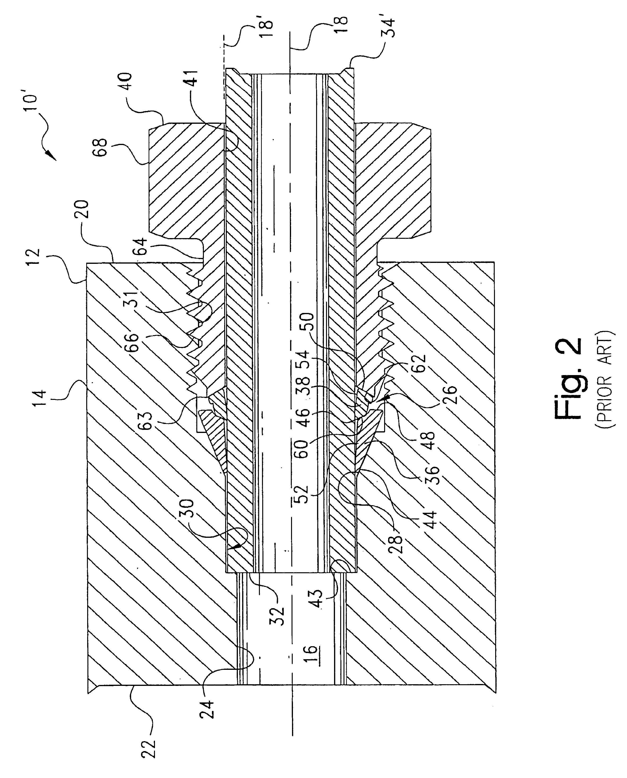
Certain terminology may be employed in the following description for convenience rather than for any limiting purpose. For example, the terms “forward” and “rearward,”“front” and “rear,”“right” and “left,”“upper” and “lower,”“top” and “bottom,” and “right” and “left” designate directions in the drawings to which reference is made, with the terms “inward,”“inner,”“interior,” or “inboard” and “outward,”“outer,”“exterior,” or “outboard” referring, respectively, to directions toward and away from the center of the referenced element, the terms “radial” or “vertical” and “axial” or “horizontal” referring, respectively, to directions or planes perpendicular and parallel to the longitudinal central axis of the referenced element, and the terms “downstream” and “upstream” referring, respectively, to directions in and opposite that of fluid flow. Terminology of similar import other than the words specifically mentioned above likewise is to be considered as being used for purposes of convenie...


PUM


Abstract

A fitting for the connection of a tubing end. The fitting includes a body having a bore with an internally-threaded opening which extends to a seating surface, and a front ferrule which is receivable coaxially over the tubing end. An externally-threaded nut is receivable coaxially over the outer diameter of the tubing end to be positionable thereon rearwardly of the front ferrule such that, with the tubing end and front ferrule being inserted through the bore opening, the nut is threadably engageable with the body urging an outer surface of the ferrule into a canning engagement against the body seating surface. The axial length of the seating surface is provided to extend substantially the entire length of the ferrule outer surface so as to constrain the radial outward expansion of the ferrule rearward end.

Description

BACKGROUND OF THE INVENTIONThe present invention relates generally to compression fittings for coupling the end of a length of tubing to another member, and more particularly to such a fitting which is of a ferruled-variety and which is particularly adapted for use with hardened or other tubing used in “medium” pressure applications.Compression fittings of a ferruled-type are widely employed in a variety of instrumentation, pneumatic, hydraulic, process, power, refrigeration, and other fluid transport applications utilizing plastic or metal tubing. Typically employing one or two ferrules for gripping the tubing and forming a fluid-tight seal between the tubing and the fitting body, these fittings have been adapted for use as connectors with many different tubing types including plastics such as polyurethane (PU), polytetrafluoroethylene (PTFE), fluorinate ethylene polypropylene (FEP), perfluoroalkoxy resin (PFA), polyethylene (PE), polypropylene (PP), rigid and flexible nylon, acryl...

Claims


Application Information

Patent Timeline
IPC IPC(8): F16L19/00F16L19/10
CPCF16L19/103
Inventor GIBSON, JAMES DAVID
Owner PARKER INTANGIBLES LLC
Why Eureka
Try Eureka