
Calibration method and apparatus using interpolation

a technology of interpolation and calibration method, applied in the field of printing machine calibration, can solve the problems of additional time delay, inability to run color calibration routines, and time-consuming color calibration techniques

Inactive Publication Date: 2005-02-08
HEWLETT PACKARD DEV CO LP
View PDF5 Cites 25 Cited by
  • Summary
  • Abstract
  • Description
  • Claims
  • Application Information

AI Technical Summary

Problems solved by technology

Techniques for color calibration may be time consuming.
Even when the patches are printed, an additional time delay is incurred as they are scanned and processed.
Of course, some people will not run these calibration routines as the time delay for printing, sensing, and processing the numerous patches is significant.
Accordingly, these printers will not be properly calibrated and will produce inconsistent colors and less-than optimal print results.

Method used


Image

  • Calibration method and apparatus using interpolation
  • Calibration method and apparatus using interpolation
  • Calibration method and apparatus using interpolation

Examples


Embodiment Construction

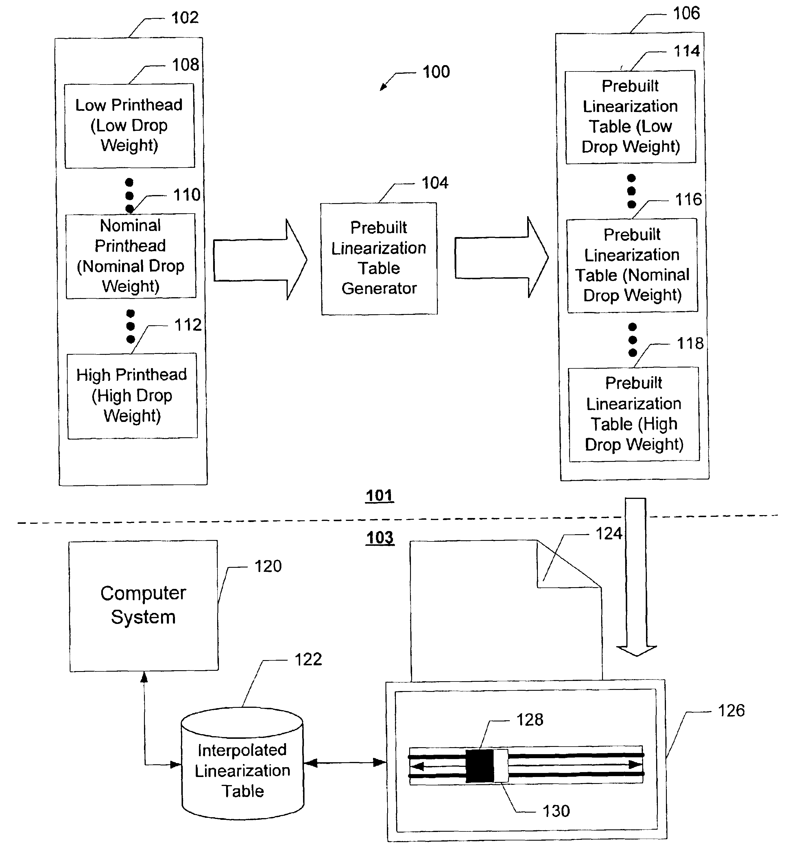
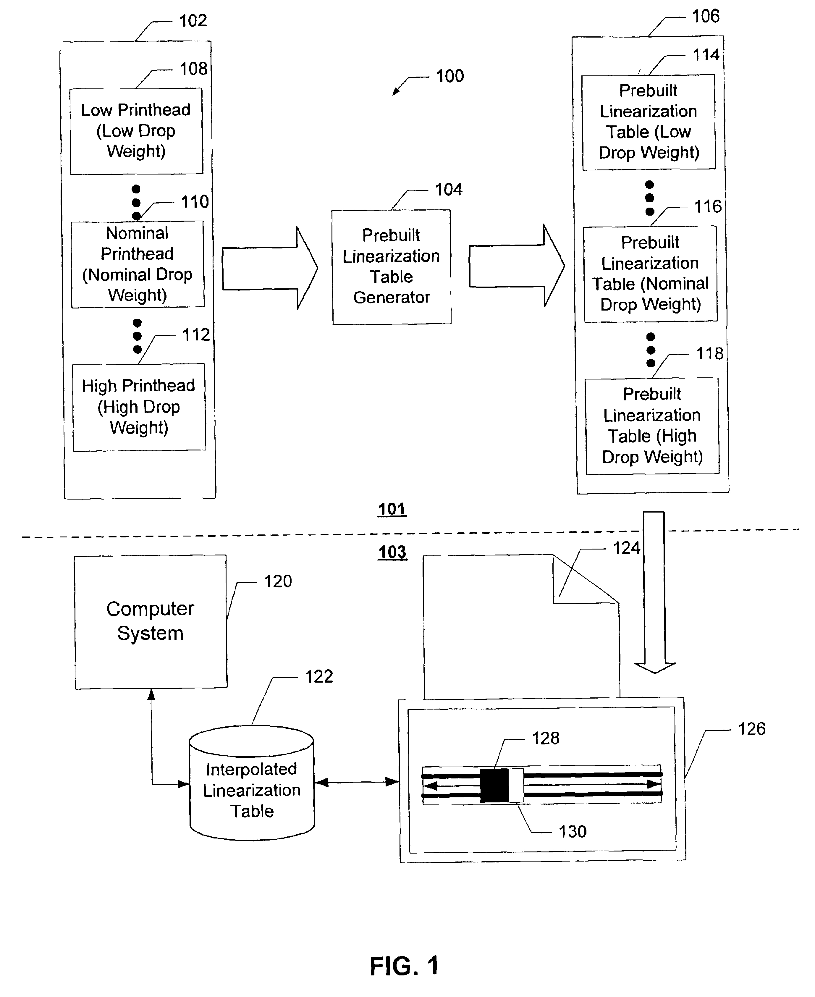
Aspects of the present invention provide one or more of the following advantages used in calibrating color printing system. First, calibration can be done more rapidly using implementations of the present invention by printing and measuring a single patch rather than a ramp of gray levels. This single patch facilitates rapid and accurate color calibration without special hardware or increased costs. Further, printers do not need to conduct paper backward to print different patches as only a single patch of the primary ink may be printed. This makes a calibration using implementations of the present invention more time and cost-effective while maintaining compatibility with a wide range of printers.

FIG. 1 is a block diagram of a printer calibration system designed in accordance with one implementation of the present invention. System 100 in FIG. 1 illustrates an offline portion 101 that operates prior to calibrating the printer and an online portion 103 used when a print head and pri...


PUM


Abstract

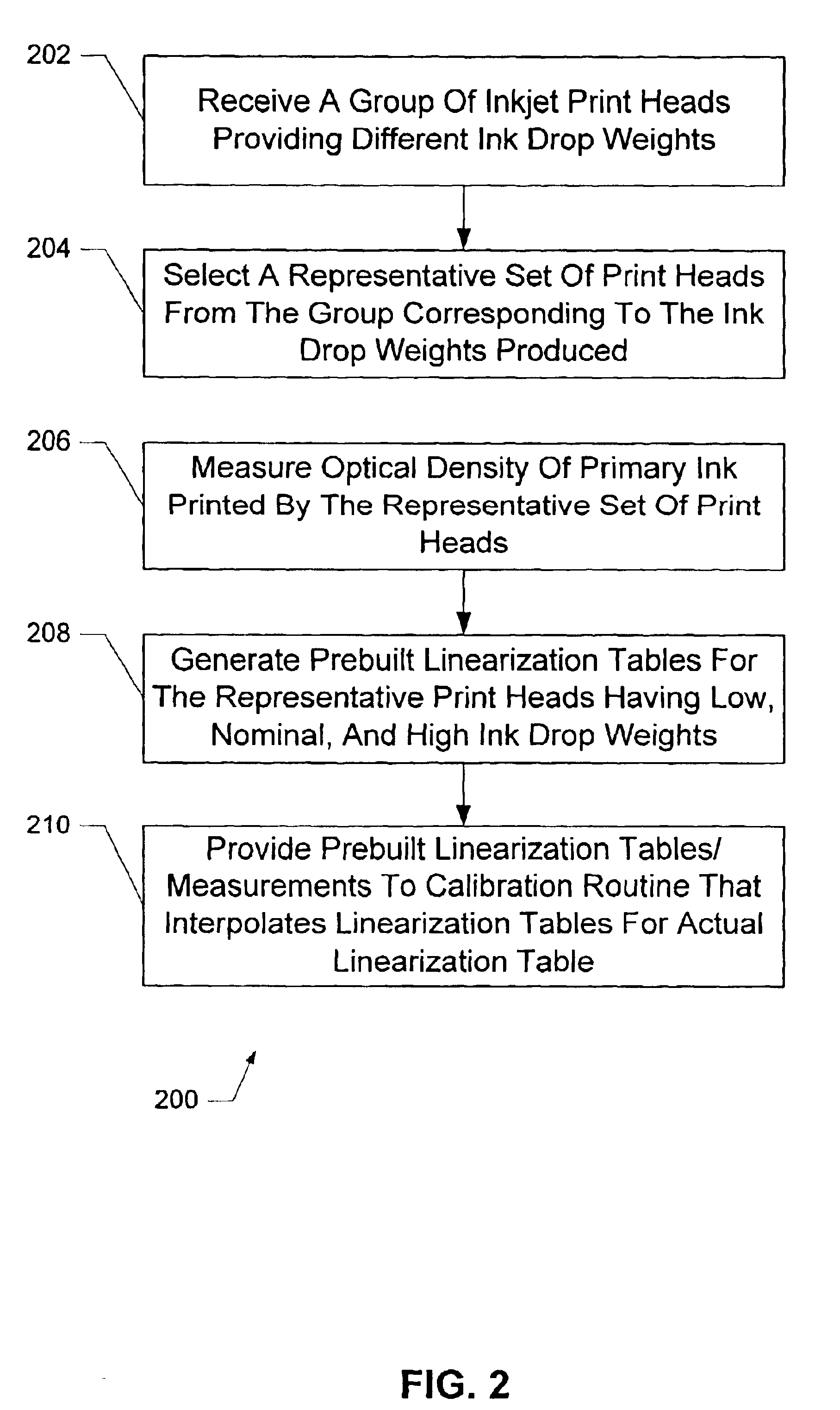
A systems and method for printer calibration creates linearization tables by receiving optical density related measurements for a primary ink in a group of one or more print heads printing with the primary ink, selecting from the group of print heads at least two print heads that deliver a range of optical densities when printing with the one or more primary ink, generating prebuilt linearization tables corresponding to the at least two print heads that compensate for different ink drop weights printed by the at least two print heads, and providing the prebuilt linearization tables and at least a portion of the optical density related measurements to a calibration routine that interpolates the prebuilt linearization tables to create an actual linearization table for the primary ink printed by a print head. The prebuilt linearization tables and measurements related to optical density calibrate a primary ink printed by a print head, by receiving two or more prebuilt linearization tables for a corresponding two or more print heads that compensate for different ink drop weights printed by the two or more print heads, determining a measurement related to optical density when the print head prints the primary ink at a selected gray level, comparing the measurement related to optical density produced by the print head with measurements related to optical density when the two or more print heads print the primary ink at the selected gray level, and estimating the linearization table for the primary ink based upon the prebuilt linearization tables for the two or more print heads and the comparison of the measurement related to optical density of the print head and the two or more print heads.

Description

BACKGROUNDPrinter calibration has become an important topic as print resolution and color reproduction improve in printers. Color calibration compensates for color inconsistency due to manufacturing variations in ink drop weight, ink chemistry and the environmental effects of temperature and humidity on the printing process. For example, ink drop weight produced by different print heads often varies as a result of minute manufacturing differences in the size of the nozzles used in an inkjet print head, different resistor characteristics in the heater element used to eject the ink droplets in the inkjet print head, variations in the orifice shape, or any other difference from one print head to another. Differences in the ink chemistry combined with temperature and humidity also affects the final color appearance when applied to a print medium. To accommodate these factors, color calibration modifies the number of ink drops during printing to make color printing more consistent.Techni...

Claims


Application Information

Patent Timeline
IPC IPC(8): H04N1/60H04N1/407B41J2/21B41J2/01
CPCH04N1/6033H04N1/4078
Inventor WU, YIFENGCOWAN, PHILIPYANG, DONGLI
Owner HEWLETT PACKARD DEV CO LP
Learn More