
Dust removal unit for a hand tool device

Inactive Publication Date: 2005-02-08
HILTI AG
View PDF17 Cites 99 Cited by
  • Summary
  • Abstract
  • Description
  • Claims
  • Application Information

AI Technical Summary

Benefits of technology

The object of the invention is to provide a robust dust removal unit incorporating a depth stop. A further object consists in the simple mounting of a dust container in the dust removal unit and on the hand tool device.
Advantageously, a dust container, preferably with an integrated bellows filter, that can be removed downwards, is arranged adjacent to the release lever, whereby a compact construction is achieved.

Problems solved by technology

The dust generated when performing drilling or chiseling work is unhealthy for the worker, creates additional workload and increases the wear and tear on hand tools.
The sensitive bellows, externally exposed, is a disadvantage, especially in the rough environment of the building trades.
The suction hose is additionally coupled with the suction head and thus creates an obstacle.
The obstructive suction hose coupled directly to the hand tool device, which conducts the dust through the hand tool device, is a disadvantage.

Method used


Image

  • Dust removal unit for a hand tool device
  • Dust removal unit for a hand tool device

Examples


Embodiment Construction

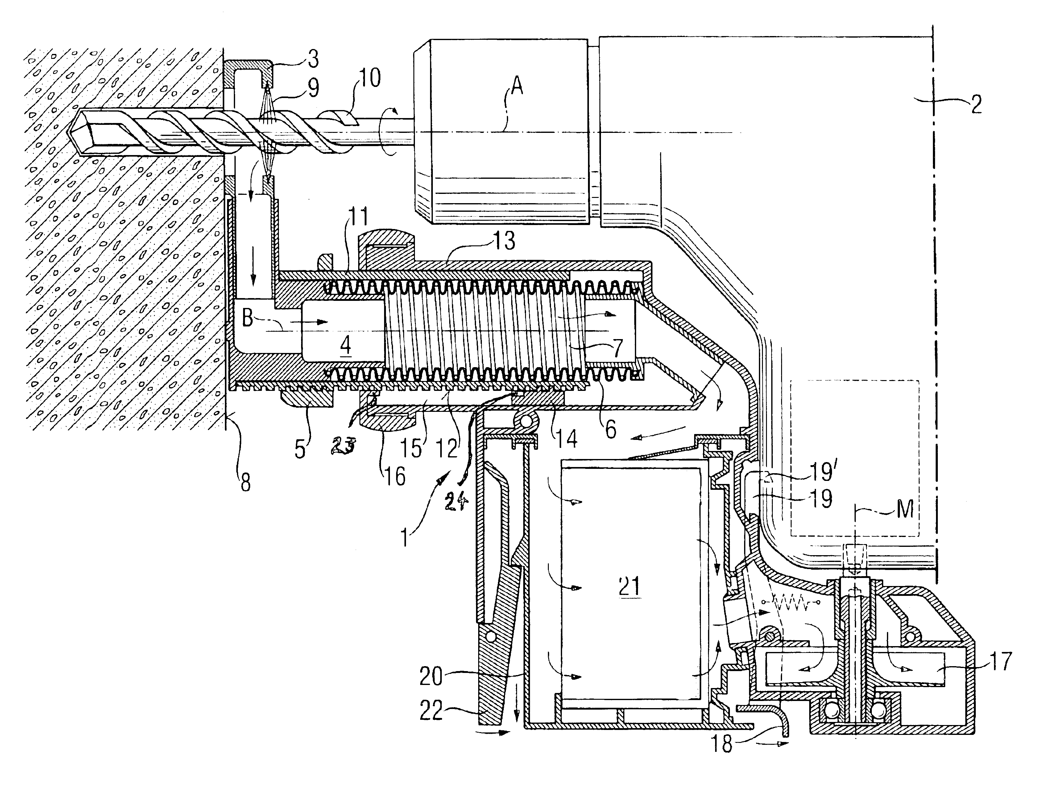
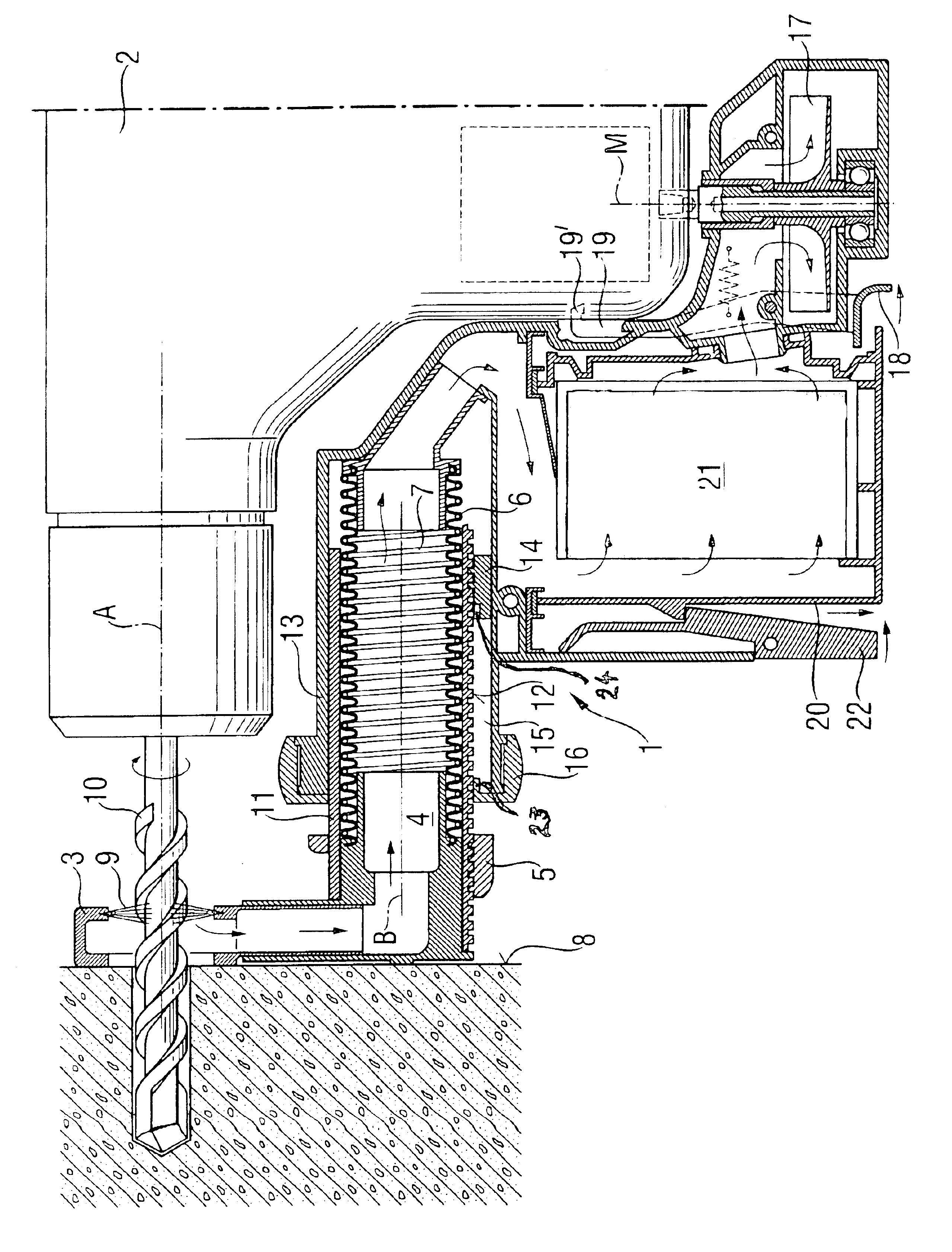
According to the drawing, a dust removal unit is mounted on a hand tool device 2, at least partially rotating around a tool working axis A. The dust removal unit 1 is characterized by a radially offset, rotationally fixed, suction tube assembly including suction tube 4 telescopable axially to a limited extent and having an axis B parallel to the working axis A and coupled at one end with a terminal suction head 3. The suction tube assembly has an adjustable axial depth stop 5. The suction tube 4 includes a pleated bellows 6 coaxial with the axis B and axially opened by an inner spring 7 and is compressed axially against a work surface 8 and abuts against the work surface in a vacuum tight manner. The suction head 3 is equipped with radially inwardly directed brushes 9 encircling working axis A, and in contact with a drilling tool 10. The suction tube assembly includes a telescoping, axially limitedly movable inner part 11 encircling the suction tube 4 and has an essentially circular...


PUM


Abstract

A dust removal unit (1) includes an adjustable axial depth stop (5) for an at least partially rotatable hand tool device (2) with a radially displaced, rotationally fixed, telescopable, axially limited movable suction tube assembly with a suction tube (4) running parallel to the axis (A) of the tool device (2) and coupled at one end to a suction head (3). The suction tube (4) includes an axially extending pleated bellows (6).

Description

FIELD OF THE INVENTIONThe invention relates to a dust removal unit for an at least partially rotating hand tool device, such as a drilling tool or a rotary hammer drill.BACKGROUND OF THE INVENTIONThe dust generated when performing drilling or chiseling work is unhealthy for the worker, creates additional workload and increases the wear and tear on hand tools.The dust suction device according to EP470048B1 is provided in the form of a unit that can be combined with the driving hand tool device, wherein a suction wheel can be rotationally fixed to a driving shaft of the hand tool device.According to DE4335417A1 a dust collector that includes a bellows-like filter element, can be fitted rotationally and pivotally into the dust suction device combined with a hand tool device and sealingly locked therein and wherein a housing portion of the dust suction device can be flipped open by means of a hinge assembly.According to DE2548100A1 the suction tube of a dust suction device is fashioned ...

Claims


Application Information

Patent Timeline
IPC IPC(8): B23Q11/00B23B47/34B25D17/18
CPCB23Q11/0046Y10T408/99Y10T408/50
Inventor EGE, MANFREDFUNFER, JOSEFMOSER, JOSEF
Owner HILTI AG
Learn More