Method of implanting an intervertebral spacer

a technology of intervertebral spacers and implants, which is applied in the field of intervertebral spacers, can solve the problems of reducing the height of the disc nucleus, affecting the natural curvature of the spine, and buckling of the anulus,

Inactive Publication Date: 2005-02-08
ORTHO DEV CORP
View PDF126 Cites 120 Cited by
  • Summary
  • Abstract
  • Description
  • Claims
  • Application Information

AI Technical Summary

Benefits of technology

It is therefore an object of the present invention to provide an intervertebral spacing system that does not require an additional, anterior surgical procedure.
The above objects and others not specifically recited are realized in a specific illustrative embodiment of an intervertebral spacer adapted for implanting between adjacent vertebral bodies of a human spine as a load-bearing replacement for a spinal disc. The spacing member includes an external, non-porous, concavo-convex contour with respect to one dimension of said spacing member. The spacing member is preferably constructed from a rigid, non-resilient load-bearing material that is incapable of elastic deformation. The spacing member is inserted with the aid of a sheathed trocar device that is releasably attached to the spacer, to enable implantation and selective positioning of the spacer by the surgeon from the posterior side of the spine, without the need to retract the dural nerve or the posterior longitudinal ligament.

Problems solved by technology

Such events cause the height of the disc nucleus to decrease, which in turn causes the anulus to buckle in areas where the laminated plies are loosely bonded.
Such practices are characterized by certain disadvantages, including a disruption in the natural curvature of the spine.
Another disadvantage of known spacing techniques and intervertebral spacers are the additional surgical complications that arise in the use of multiple spacers in a single disc space.
Placement of the multiple spacers is often too difficult to accomplish from the posterior side of the patient, at least without causing with undue trauma to the patient, because a surgeon would need to retract the dura nerve as well as the anterior longitudinal ligament, thereby increasing damage, pain and morbidity to the patient.
This patent does not address the problem of compromising the sagittal alignment, or of increased pain and trauma to the patient by implantation of multiple spacers in a single disk space.

Method used


Image

  • Method of implanting an intervertebral spacer
  • Method of implanting an intervertebral spacer
  • Method of implanting an intervertebral spacer

Examples


Embodiment Construction

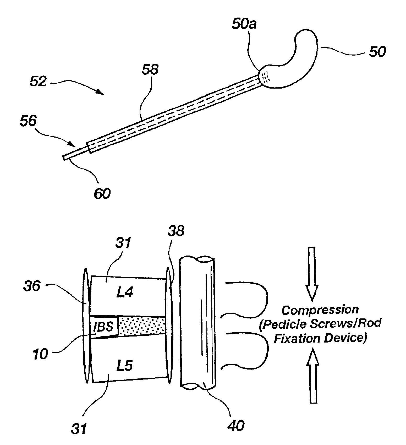
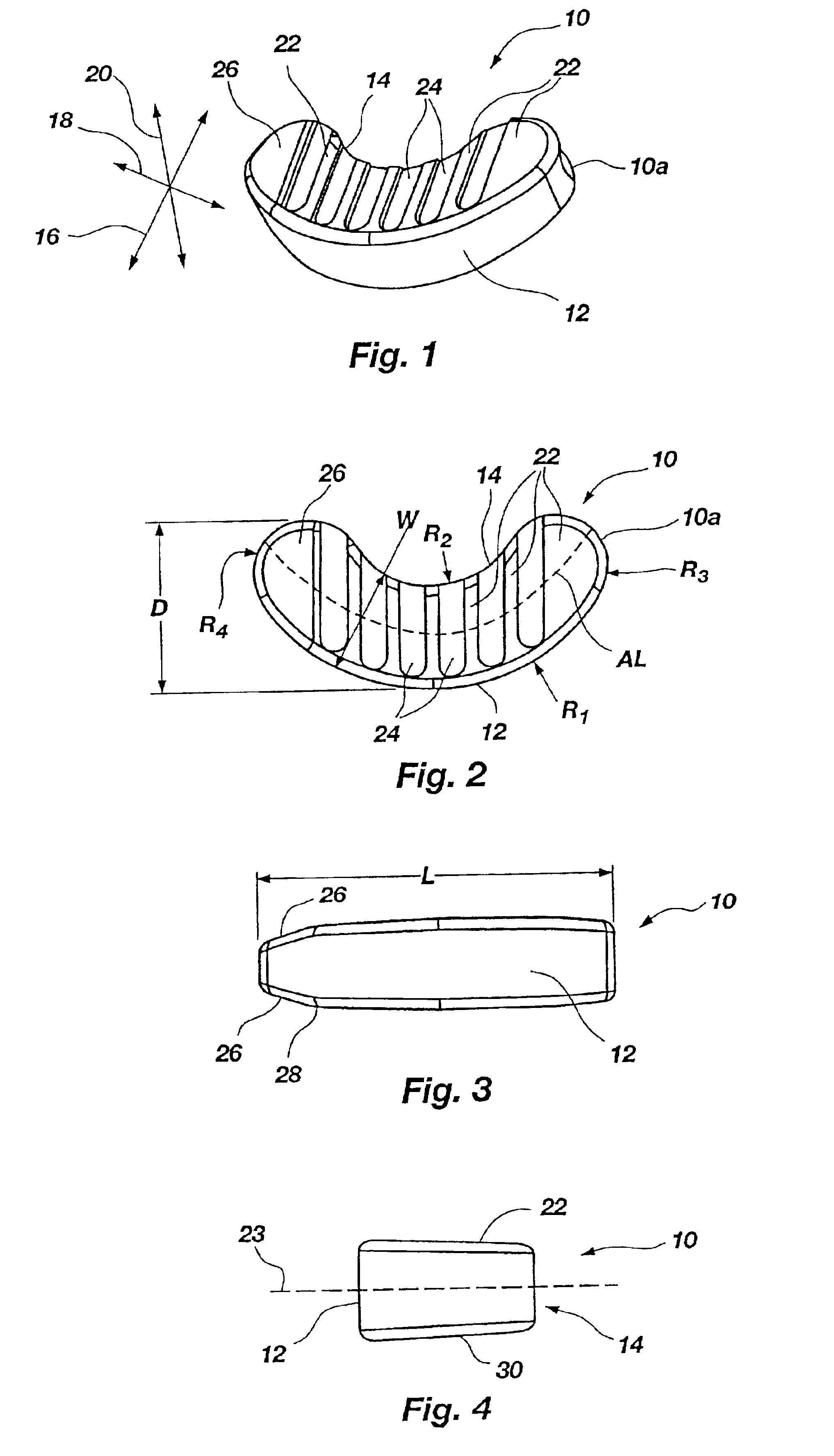
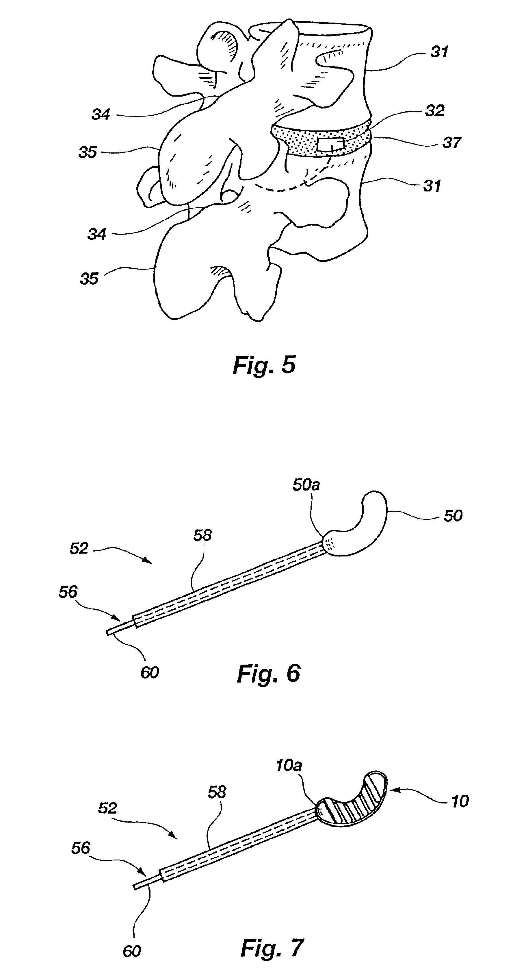
For the purposes of promoting an understanding of the principles in accordance with the invention, reference will now be made to the embodiments illustrated in the drawings and specific language will be used to describe the same. It will nevertheless be understood that no limitation of the scope of the invention is thereby intended. Any alterations and further modifications of the inventive features illustrated herein, and any additional applications of the principles of the invention as illustrated herein, which would normally occur to one skilled in the relevant art and having possession of this disclosure, are to be considered within the scope of the invention claimed.

Before the apparatus and methods of the present invention are described further, it is to be understood that the invention is not limited to the particular configurations, process steps, and materials disclosed herein as such configurations, process steps, and materials may vary somewhat. It is also to be understood...


PUM


Abstract

An intervertebral spacer adapted for implanting between adjacent vertebral bodies of a human spine as a load-bearing replacement for a spinal disc. The spacing member includes an external, non-porous, concavo-convex contour with respect to one dimension of the spacing member. The spacing member is preferably constructed from a rigid, non-resilient load-bearing material that is incapable of elastic deformation. The spacing member is inserted with the aid of a sheathed trocar device that is releasably attached to the spacer, to enable implantation and selective positioning of the spacer by the surgeon from the posterior side of the spine, without the need to retract the dural nerve or the posterior longitudinal ligament.

Description

STATEMENT REGARDING FEDERALLY SPONSORED RESEARCH OR DEVELOPMENTNot Applicable.BACKGROUND OF THE INVENTION1. The Field of the InventionThe present invention relates generally to an intervertebral spacer, and more particularly, but not necessarily entirely, to a interbody spacing system for accomplishing enhanced intervertebral fusion between adjacent vertebral bodies of a human spine.2. Description of Related ArtThe human spine is a complex, sophisticated mechanical system. The vertebrate spine operates as a structural member, providing structural support for the other body parts. A normal human spine is segmented with seven cervical, twelve thoracic and five lumbar segments. The lumbar portion of the spine resides on the sacrum, which is attached to the pelvis. The pelvis is supported by the hips and leg bones. The bony vertebral bodies of the spine are separated by intervertebral discs, which reside sandwiched between the vertebral bodies and operate as joints allowing known degree...

Claims


Application Information

Patent Timeline
Patent Type & Authority Patents(United States)
IPC IPC(8): A61F2/28A61F2/44A61F2/46A61F2/30A61F2/00
CPCA61F2/28A61F2/442A61F2/4465A61F2/4611A61F2/4684A61F2002/2835Y10S623/908A61F2002/30774A61F2002/30828A61F2002/4627A61F2230/0015A61F2310/00023A61F2310/00179A61F2002/30133
Inventor VARGA, PETER PALOGILVIE, JAMES A.
Owner ORTHO DEV CORP
Why Eureka
Try Eureka