

DNA isolation method
- Summary
- Abstract
- Description
- Claims
- Application Information
AI Technical Summary
Benefits of technology
Problems solved by technology
Method used
Image

Examples
example 1
In a specific experiment the following steps were taken in which liquids were introduced into the micro-channel by suction:
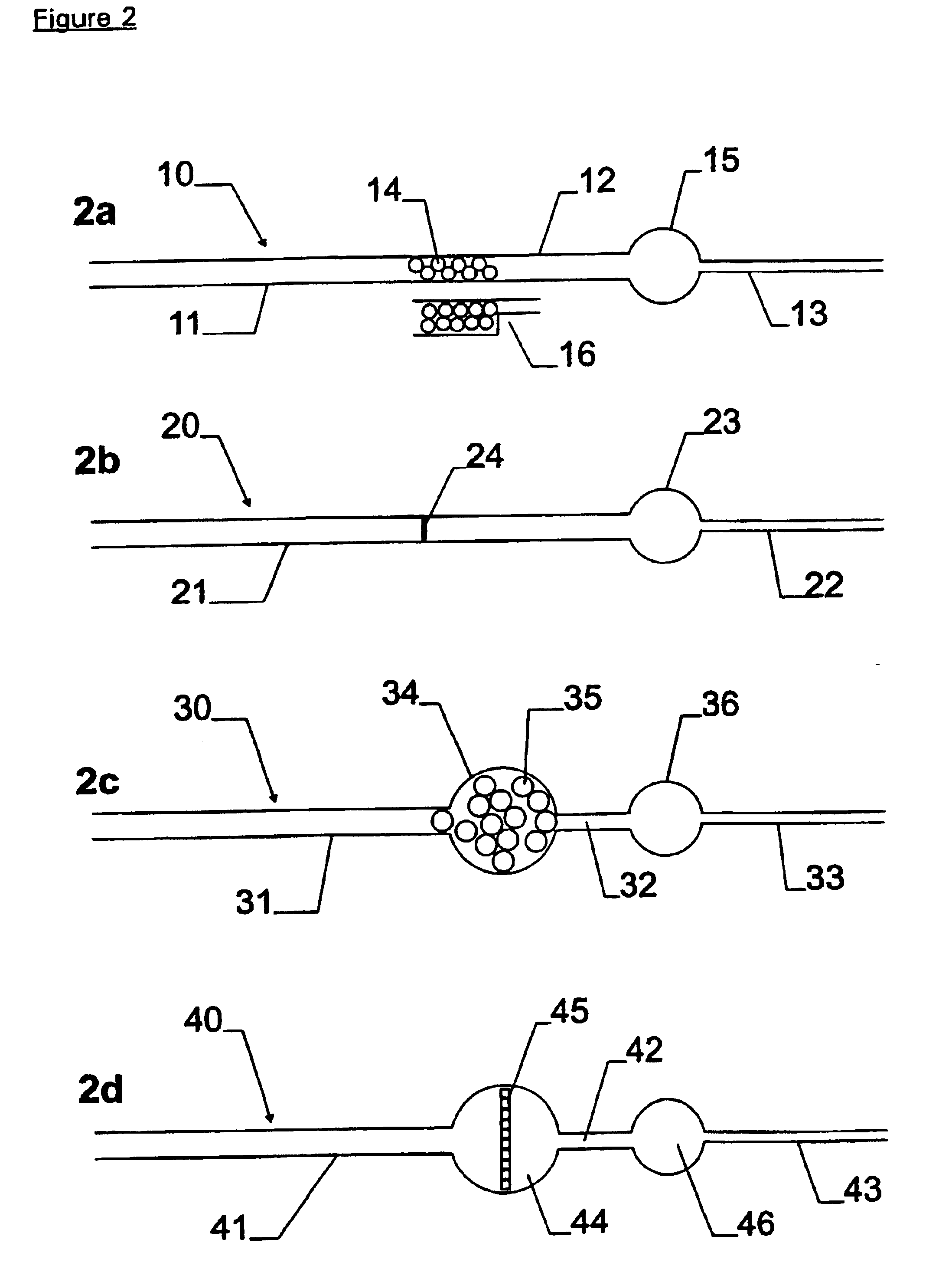
A micro-channel of the following dimensions (4000 μm long×120 μm wide with a depth of 60 μm for half the length and 10 μm for the rest of the channel) was loaded with a small volume of rigid monodisperse spherical plastic beads (polystyrene cross-linked with underivatised divinylbenzene, SOURCE™ particles, Amersham Pharmacia Biotech) with a diameter of 15 μm. These formed a thin layer of beads at the interface between the deep and shallow regions of the micro-channel (see FIG. 2a).
5 μl of whole EDTA blood were mixed with an equal volume of Lysis Buffer containing 10 mM Tris pH 8.0, 320 mM sucrose, 5 mM MgCl2 and 1% (v / v) Triton X-100, and incubated at room temperature for 5 minutes. The lysate was diluted ten-fold with a 1:1 mixture of Lysis Buffer and Phosphate Buffered Saline (PBS, Sigma). A volume of 0.4 μl of the diluted lysate was drawn through the micro-ch...
example 2
DNA was isolated from frozen citrate blood on a shallow bead bed as in described in Example 1 except that it was not visualised with PicoGreen. In this case a somewhat larger channel was used (4000 μm long×650 μm wide with a depth of 55 μm for half the length and 10 μm for the rest of the channel).
A solution containing the following reagents was introduced into the chamber to lyse the nuclei and release the DNA: 10 mM Tris / HCl, pH 8; 0.5% SDS; 1 mg / ml Proteinase K. The reaction mixture was incubated at 55° C. for 5 minutes. The contents of the chamber were washed out with 1 μl of a solution containing the following components: 1×PCR Buffer II (Perkin Elmer ABI); 6% (w / v) α-cyclodextrin (Aldrich). The resulting liquid was collected and diluted to 10 μl with water.
PCR was run on the extracted DNA as follows:
Five microlitres of diluted DNA were added to a PCR mixture (final volume 25 μl) containing the following components: 1×PCR buffer II (Perkin Elmer ABI); 1.5 mM MgCl2; 200 μM deoxy...
PUM
| Property | Measurement | Unit |
|---|---|---|
| Flow rate | aaaaa | aaaaa |
Abstract
Description
Claims
Application Information