Surgical Tool For Removing A Block Of Tissue From An Organ

Inactive Publication Date: 2008-11-13
D O T & OPHTHALMIC TECH
View PDF3 Cites 3 Cited by
  • Summary
  • Abstract
  • Description
  • Claims
  • Application Information

AI Technical Summary

Benefits of technology

[0024]According to a further feature of the present invention, the locking tab and the lateral recess are d

Problems solved by technology

While this approach has been found effective, it may be at risk of non-uniform results due to variations in the mechanical

Method used


Image

  • Surgical Tool For Removing A Block Of Tissue From An Organ
  • Surgical Tool For Removing A Block Of Tissue From An Organ
  • Surgical Tool For Removing A Block Of Tissue From An Organ

Examples


Example

[0036]The present invention is a surgical tool for removing a block of tissue or other material from an organ or other body.

[0037]The principles and operation of surgical tools according to the present invention may be better understood with reference to the drawings and the accompanying description.

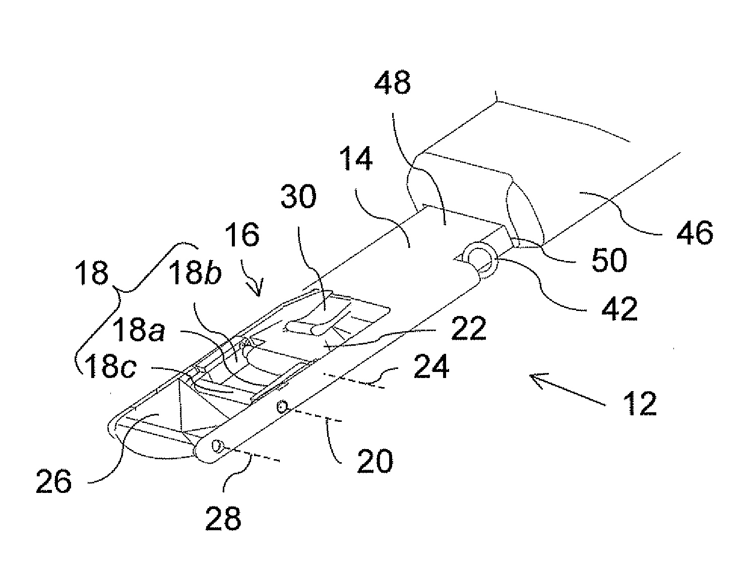
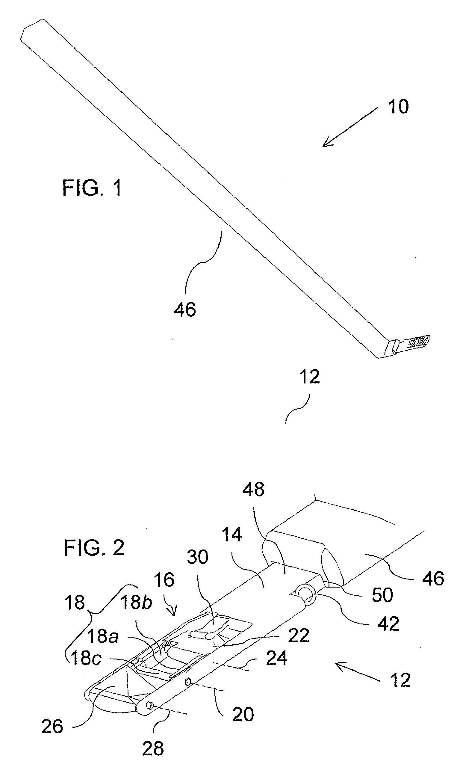
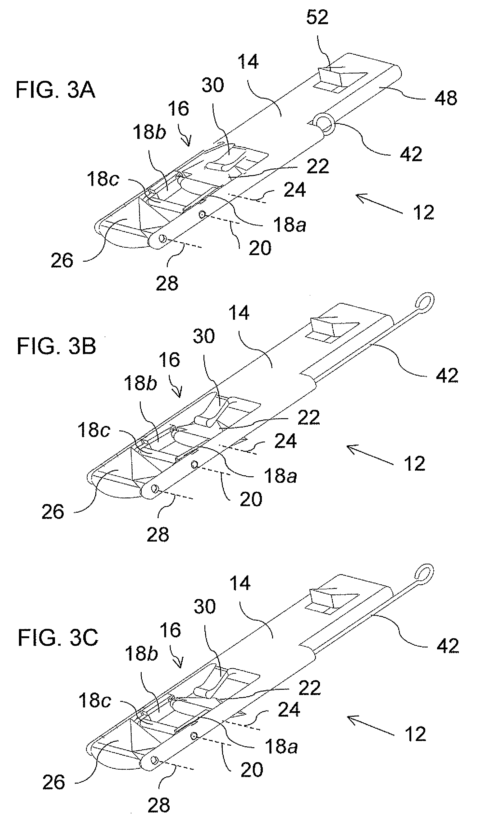
[0038]Referring now to the drawings, FIGS. 1-6D illustrate the structure and function of a surgical tool, generally designated 10, constructed and operative according to the teachings of the present invention, while FIGS. 7A-7F illustrate the use of tool 10 for removal of a block of material from a body, in a particularly preferred but non-limiting example of the human eye.

[0039]Generally speaking, tool 10 has a tool head 12 including an elongated support element 14 configured for insertion along a first slit parallel to a direction of elongation of support element 14 into the tissue of the organ. A first blade assembly 16 includes a pair of arms 18a, 18b which are pivotally mounted rela...


PUM


Abstract

A surgical tool for removing a block of tissue or other material from an organ or other body has an elongated support element which carries a first blade assembly including a pair of arms pivotally mounted about a first transverse axis, and a first blade element pivotally mounted to the arms. A second blade element is also pivotally mounted to the support element. A mechanical actuation arrangement is configured to resiliently bias the first blade assembly and the second blade element from in-plane positions towards deflected positions for initiating a predefined cutting sequence for removal of the block of tissue.

Description

FIELD AND BACKGROUND OF THE INVENTION[0001]The present invention relates to surgical devices and, in particular, it concerns a surgical tool for surgical tool for removing a block of tissue or other material from an organ or other body.[0002]U.S. Pat. No. 7,041,114 to the present inventor describes a surgical method for removing a piece of tissue from within soft body tissue, and particularly, for extracting a tissue block from the angle of the eye, as well as corresponding surgical tools. The technique described therein is highly advantageous, providing reliable extraction of a block of tissue with a well defined shape and dimensions through a small incision. In the context of the ocular surgery procedure described, extraction of a block of trabecular tissue is achieved via a corneal approach through a self-sealing flap, thereby avoiding trauma to vascularized tissue of the eye. The aforementioned patent is hereby incorporated by reference as if fully set out herein.[0003]Despite t...

Claims


Application Information

Patent Timeline
IPC IPC(8): A61B17/32
CPCA61B17/320016A61F9/0133A61F9/00781A61B2017/00969
Inventor DAN, JACOB
Owner D O T & OPHTHALMIC TECH
Why Eureka
Try Eureka