Built-in electric heating structure for a travel mug or thermos bottle

a technology of thermos bottles and built-in electric heating, which is applied in the field of built-in electric heating structures of thermos bottles, can solve the problems of increased production costs, poor heating efficiency, and vulnerable inner cases b>70/b>, and achieve the effect of preventing overheating of film heaters

Inactive Publication Date: 2005-02-08
J SHENG
View PDF12 Cites 94 Cited by
  • Summary
  • Abstract
  • Description
  • Claims
  • Application Information

AI Technical Summary

Benefits of technology

In keeping with the principle of the present invention, the foregoing objective of the present invention is attained by a travel mug or thermos bottle, which comprises an outer case, an inner case, a spacer, a pliable film heater, and a temperature control device. The inner case is made of a material which is an excellent conductor of heat. The inner case is fitted into the outer case in conjunction with the spacer such that an air space is formed between the inner case and the outer case, with the air space acting

Problems solved by technology

Such a prior art travel mug as described above is defective in design in that the assembly of the travel mug is done along with the aluminium foil cover 73 and the thermal insulation material 72, thereby resulting in an increase in production cost.
In addition, the heating efficiency is poor due to the limited co

Method used


Image

  • Built-in electric heating structure for a travel mug or thermos bottle
  • Built-in electric heating structure for a travel mug or thermos bottle
  • Built-in electric heating structure for a travel mug or thermos bottle

Examples


Embodiment Construction

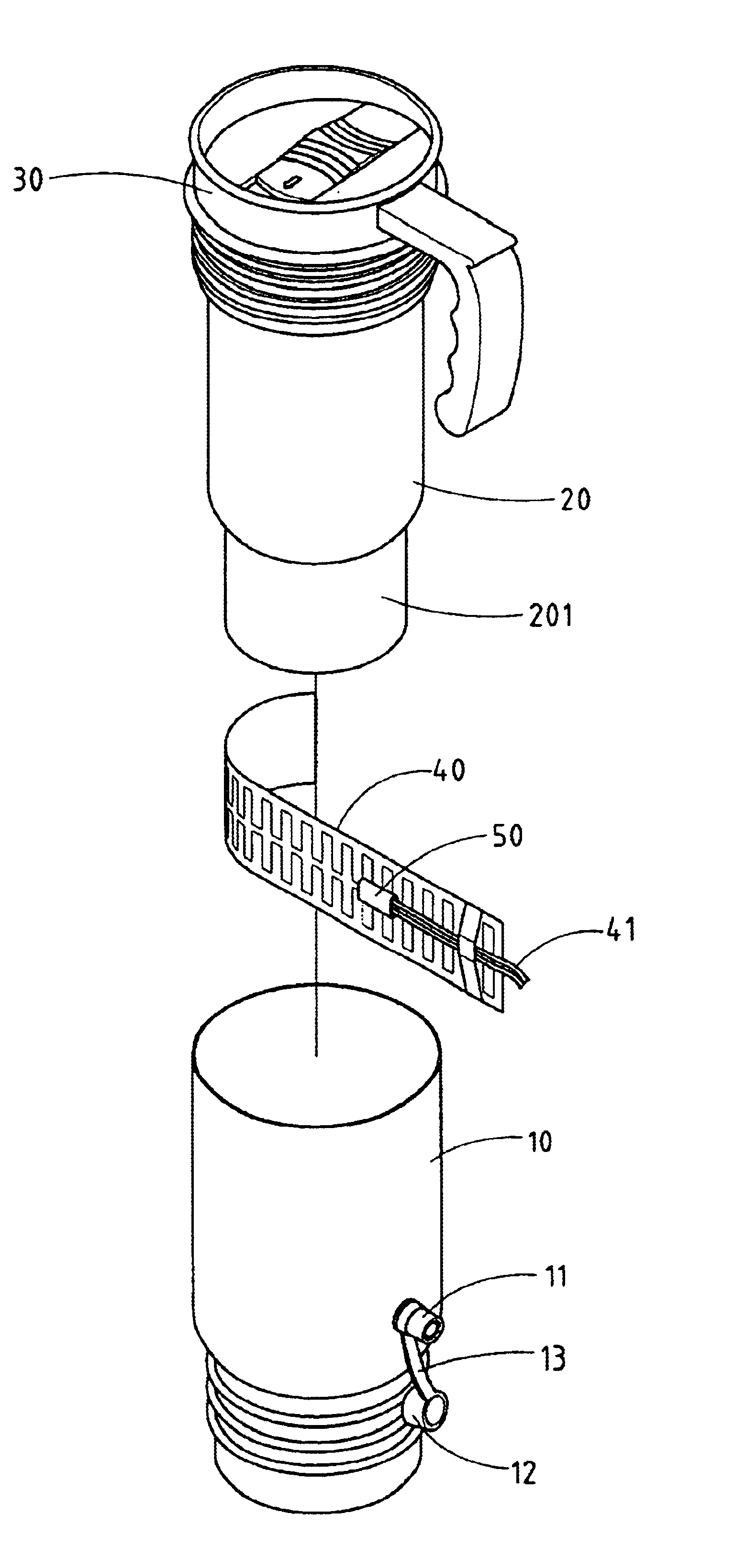
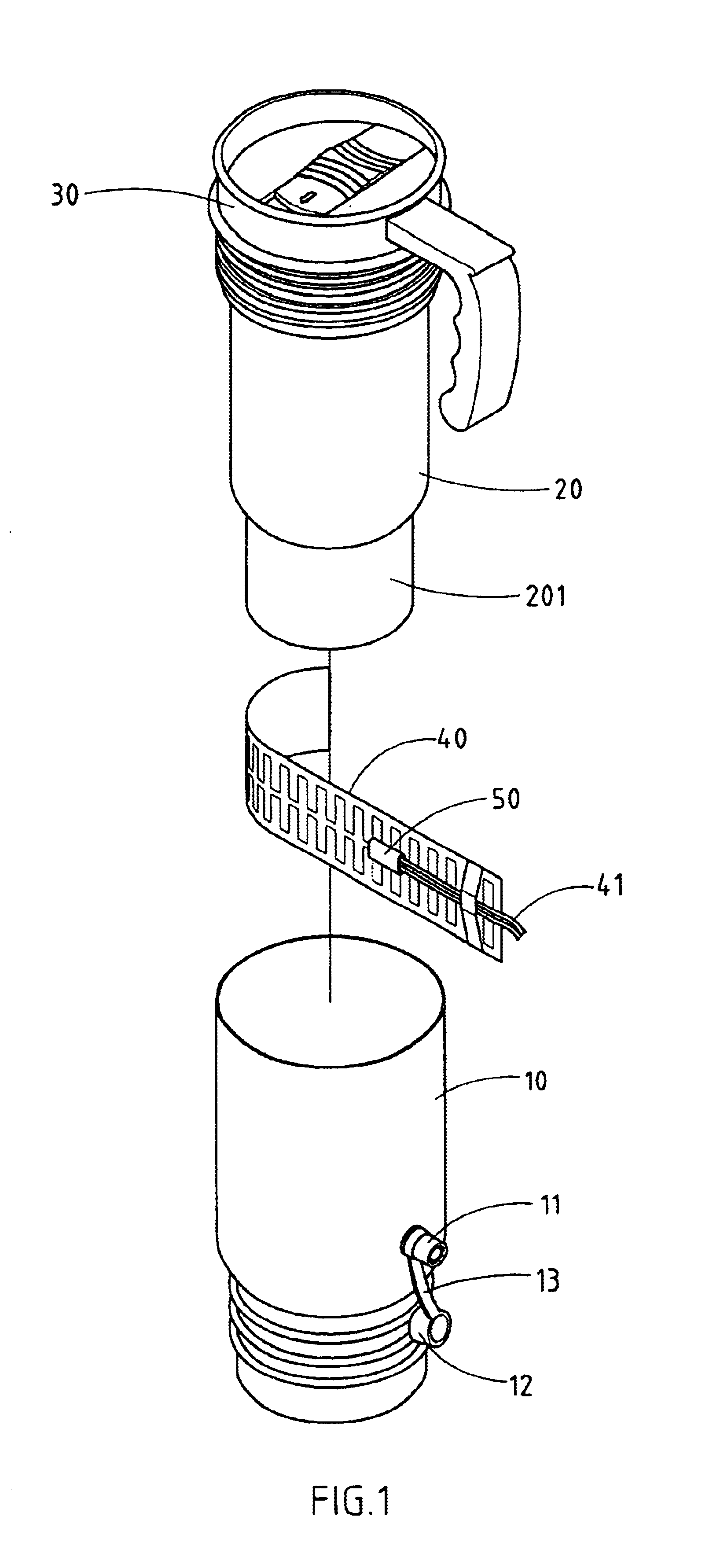
As shown in FIGS. 1-6, a travel mug embodied in the present invention comprises an outer case 10, an inner case 20, a spacer 30, a pliable film heater 40, a temperature control device 50, and a power source connector 60.

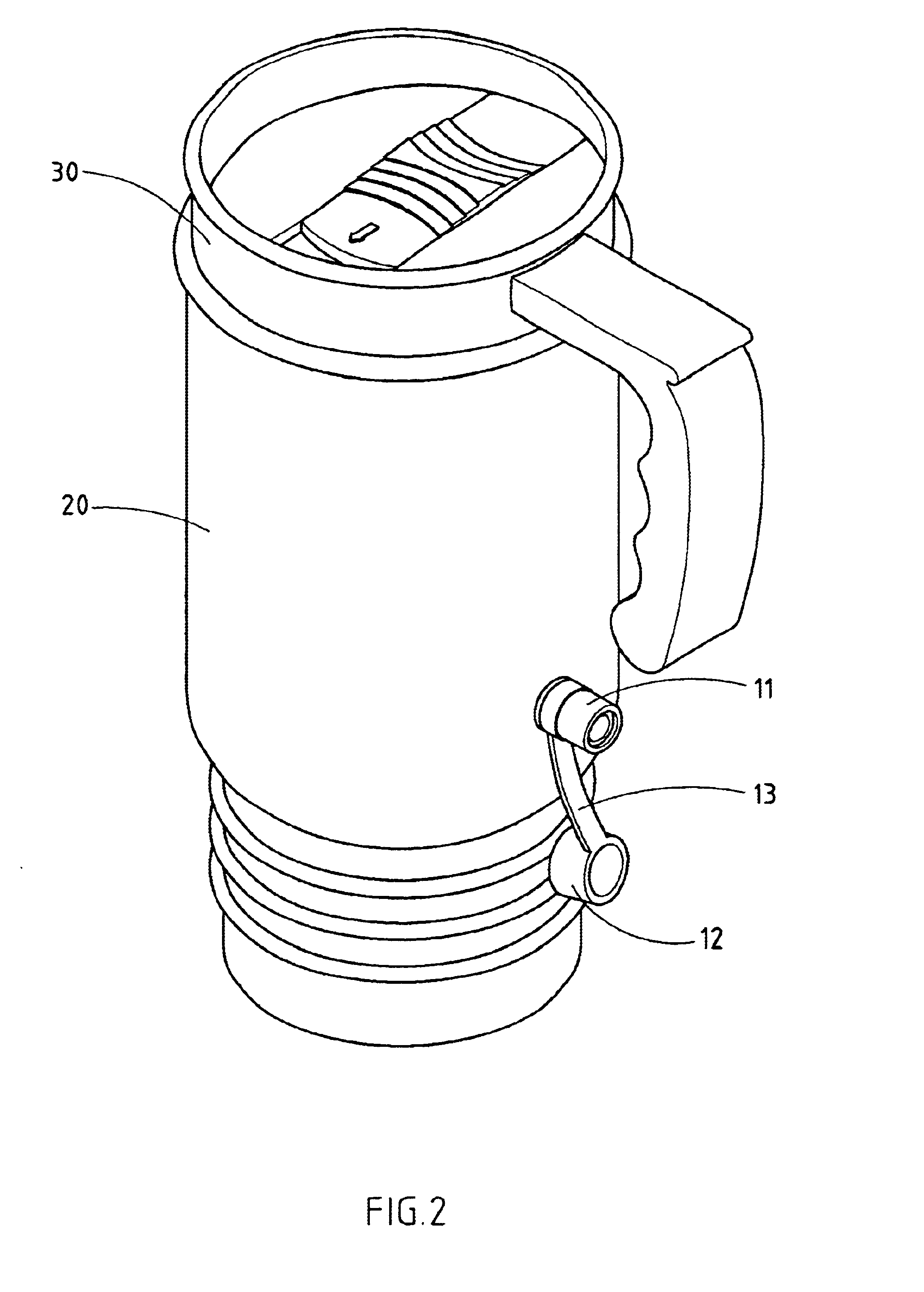
The outer case 10 is provided with a receptacle 11, a protective cover 12 removably fitted over the receptacle 11, and a soft strap 13 which is fastened at one end with the outer case 10 and at the other end with the protective cover 12.

The inner case 20 is made of a heat-conductible material and is fitted into the outer case 10 in conjunction with the spacer 30 of a plastic material, which is disposed between the top end of the inner case 20 and the top end of the outer case 10, thereby resulting in formation of an air space 15 for insulation to help retain heat, as shown in FIG. 3. The inner case 20 of the present invention may be made of a metal material, or plastic material capable of withstanding high temperatures.

The pliable film heater 40 is intimately attache...


PUM


Abstract

A travel mug has an outer case, an inner case, a film heater, a temperature control device, and a power source connector. The inner case is fitted into the outer case in conjunction with a spacer, thereby resulting in formation of an air space insulation between the inner case and the outer case. The film heater is fastened to the bottom end of the inner case and is connected to an electrical receptacle of the outer case by a wire which is also connected with the temperature control device located in proximity of the film heater. The receptacle is connected to a power source by the power source connector.

Description

RELATED U.S. APPLICATIONSNot applicable.STATEMENT REGARDING FEDERALLY SPONSORED RESEARCH OR DEVELOPMENTNot applicable.REFERENCE TO MICROFICHE APPENDIXNot applicable.FIELD OF THE INVENTIONThe present invention relates generally to a travel mug or thermos bottle, and more particularly to a built-in electric heating structure of the travel mug or thermos bottle.BACKGROUND OF THE INVENTIONAs shown in FIGS. 8 and 9, a travel mug of the prior art comprises an inner case 70, an outer case 71, a thermal insulation material 72, and a heating coil 74. The inner case 70 is made of a plastic material and is fitted into the outer case 71 along with the thermal insulation material 72 which is located between the inner case 70 and the outer case 71. The inner case 70 is provided at the bottom end with an aluminum foil cover 73 which is encircled by the heating coil 74. The heating coil 74 is connected to a power source cord 76 via a through hole 75 of the outer case 71.Such a prior art travel mug ...

Claims


Application Information

Patent Timeline
IPC IPC(8): A47J41/00A47J36/24
CPCA47J41/005A47J36/2472
Inventor LIU, CHIH-HSIANGLI, SHU-FEN
Owner J SHENG
Why Eureka
Try Eureka