Switch/volume control assembly

a technology of volume control and switch, which is applied in the direction of resistors, lighting and heating apparatus, contacts, etc., can solve the problems of malfunction of hearing instruments, and it is not easy to integrate the device of u.s. patent no. 3,195,358 in the outer wall of another small device/apparatus, such as a hearing aid, and achieves waterproof environment and easy removal from the apparatus

Inactive Publication Date: 2005-02-08
SONION ROSKILDE
View PDF27 Cites 85 Cited by
  • Summary
  • Abstract
  • Description
  • Claims
  • Application Information

AI Technical Summary

Benefits of technology

It is a disadvantage of the inventions disclosed in the above-mentioned references that the member to be used in activating the device is not encapsulated, or at least partly encapsulated, in a housing—see e.g. the rotatably mounted member 30 in FIG. 2 of U.S. Pat. No. 3,195,358. This non-encapsulated member makes it rather difficult to integrate the device of U.S. Pat. No. 3,195,358 in an outer wall of another small device / apparatus, such as a hearing aid.
It is an object of the present invention to provide a switch or volume control to be inserted into an apparatus, and wherein the switch provides a waterproof environment for the electrical parts of the apparatus and switch / volume control.
According to a first aspect, the present invention relates to a switch or volume control assembly to be mounted in a wall of an apparatus, such as a hearing aid, said assembly comprising:a housing having an inner sidewall comprising connection parts for providing a waterproof connection between the housing and the wall of the apparatus,an inner portion bounded by an inner sidewall and positioned inside said housing, said inner sidewall and said outer sidewall being separated by a groove,one or more electrical terminals extending from outside the housing into said inner portion, so as to form one or more contact areas on a surface within said inner portion,a contact member positioned inside said inner portion for providing continuous or periodical contact between said contact area(s) and / or between contact area(s) and the contact member, anda movable member positioned inside the housing and between at least two detachable parts defining the exterior of the housing, the movable member having a part extending out of the housing, and the movable member engaging said contact member so as to move the contact member with the movable member.
Preferably, the housing may be defined by two detachable parts. The detachable parts may be screwed, glued or electric welded together.
By using the flexible print circuit strip, the switch can easily be removed from the apparatus by loosening the clamp.

Problems solved by technology

Penetration of liquids—e.g. water or sweat running from the scalp into e.g. electrical contacts will typically result in malfunctions of the hearing instrument.
It is a disadvantage of the inventions disclosed in the above-mentioned references that the member to be used in activating the device is not encapsulated, or at least partly encapsulated, in a housing—see e.g. the rotatably mounted member 30 in FIG. 2 of U.S. Pat. No. 3,195,358.
This non-encapsulated member makes it rather difficult to integrate the device of U.S. Pat. No. 3,195,358 in an outer wall of another small device / apparatus, such as a hearing aid.

Method used


Image

  • Switch/volume control assembly
  • Switch/volume control assembly
  • Switch/volume control assembly

Examples


Embodiment Construction

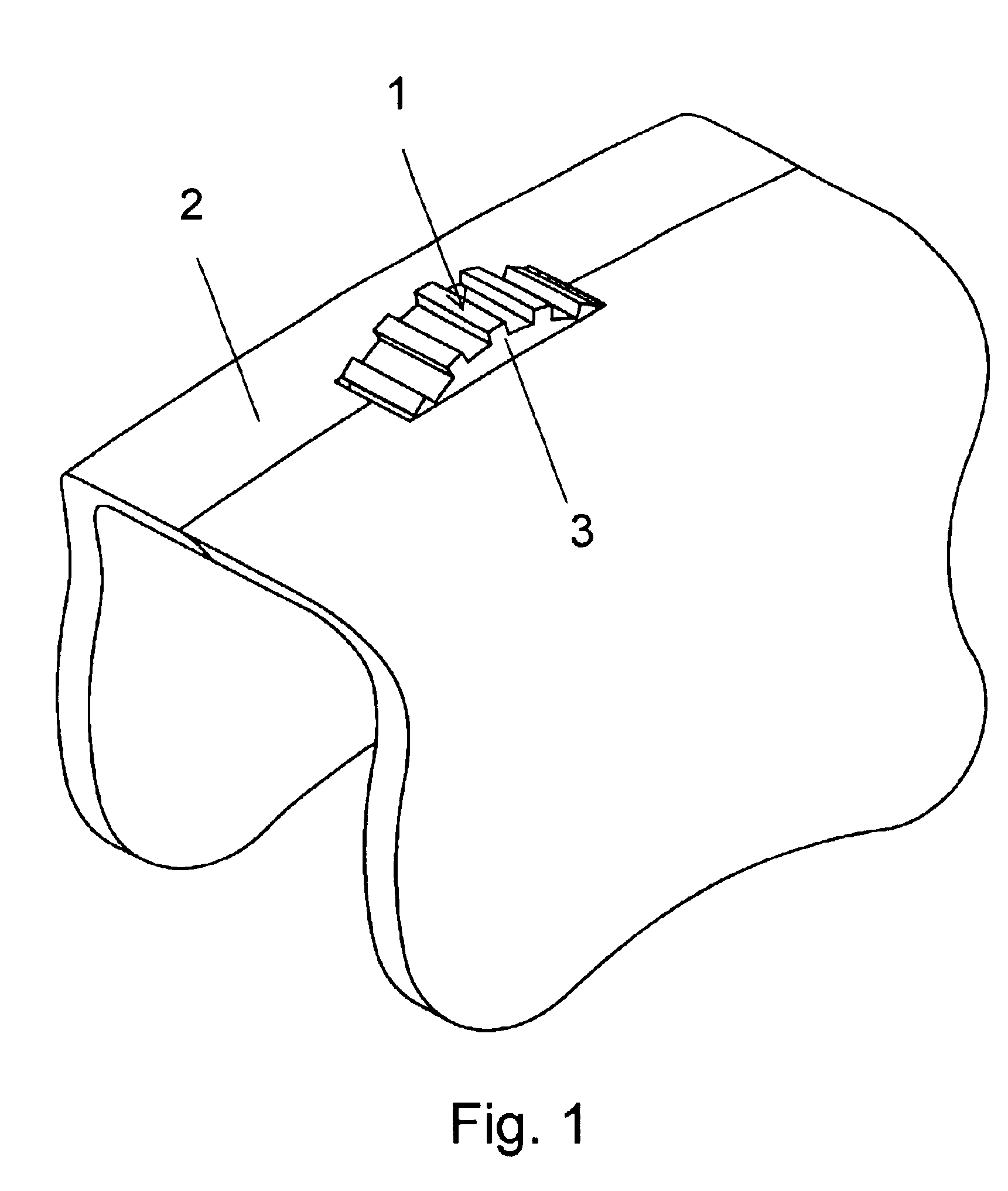
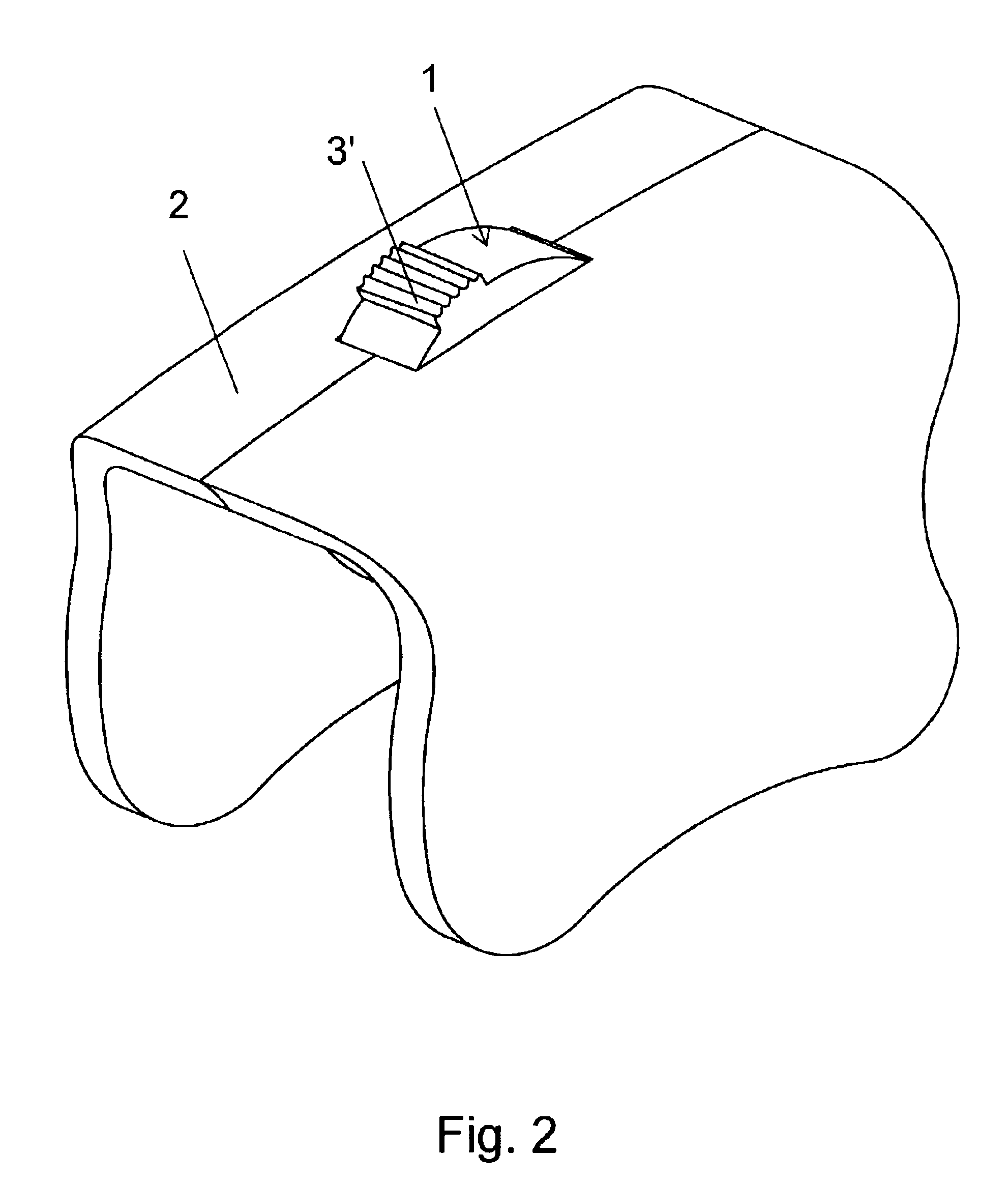
FIGS. 1-2 show a sidewall 2 of a hearing aid in which the switch assembly 1 is mounted. The assembly is operated by rotation of the wheel 3. In FIG. 1 the assembly composes a wheel 3 (e.g. volume control) and in FIG. 2 it composes a switch / contact 3′.

FIG. 3 shows the housing 4 of the assembly mounted in the sidewall 2. The housing 4 comprises flanges 5 that engage with recesses 6 in the sidewall and thus provide a waterproof connection therebetween.

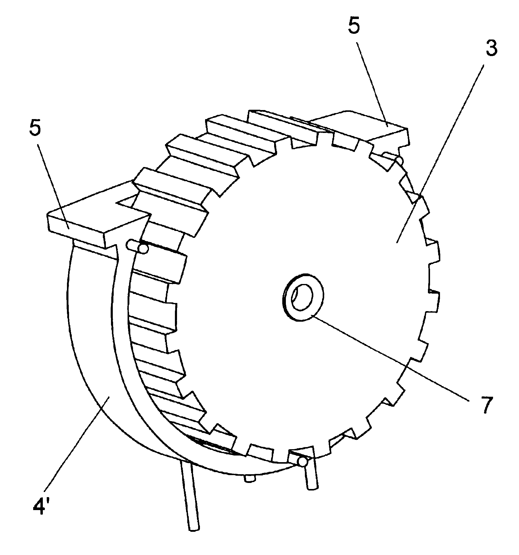
FIG. 4 shows the assembly comprising a mill wheel 3 (e.g. a volume control) mounted on the axle 7 that is mounted to one (4′) of two detachable parts of the housing. The housing comprising flanges 5.

FIG. 5 shows the assembly wherein the mill wheel 3 of FIG. 4 is removed. An encoder 8 is positioned inside the inner wall portion 9 of the inner portion of the housing. The encoder 8 engages with the wheel 3 (see FIG. 4) when the wheel is mounted in the housing, whereby the encoder is turned when turning the wheel. The encoder gets in touch wi...


PUM


Abstract

The present invention relates to switch or volume control assemblies, in particular to switch or volume control assemblies to be mounted in e.g. hearing aids, said assembly comprising a movable member, such as a wheel-like member positioned between at least two detachable parts defining the exterior of a housing, the movable member having a part extending out of the housing, the movable member engaging a contact member so as to move the contact member with the movable member.

Description

FIELD OF THE INVENTIONThe invention relates to a switch / volume control assembly to be inserted in an apparatus, in particular hearing aids, the assembly providing a moisture-protection for the electrical parts of the switch and apparatus.BACKGROUND OF THE INVENTIONLiquid running into the electrical parts is one of the parameters affecting the lifetime and operability of electronic instruments, such as hearing aids. Penetration of liquids—e.g. water or sweat running from the scalp into e.g. electrical contacts will typically result in malfunctions of the hearing instrument.U.S. Pat. No. 3,195,358 discloses weather-tight instrument housings and assemblies for switches, potentiometers and the like. The modular unit of the instrument housings includes a basic housing portion having substantially parallel front and back sides and a generally cylindrical cavity for containing adjustable electrical mechanism formed in the back surface.U.S. Pat. No. 4,081,782 discloses a potentiometer and s...

Claims


Application Information

Patent Timeline
Patent Type & Authority Patents(United States)
IPC IPC(8): H01C10/36H01C10/00H01H19/06H01H19/00
CPCH01C10/36H01H19/001H01H19/06H01H2300/004H01H2001/5816H01H2019/146
Inventor JORGENSEN, MARTIN BONDOVIDEB.AE BUTTED.K, KARSTEN
Owner SONION ROSKILDE
Why Eureka
Try Eureka