
Digital camera having specifiable tracking focusing point

a technology of focusing point and digital camera, which is applied in the field of digital cameras, can solve the problems of inability to apply a technique in practical use and the calibration of individual differences, and achieve the effects of improving the operability of digital cameras, reducing the magnification of subject images, and improving the operability of specifying factors

Inactive Publication Date: 2005-02-08
MINOLTA CO LTD
View PDF22 Cites 32 Cited by
  • Summary
  • Abstract
  • Description
  • Claims
  • Application Information

AI Technical Summary

Benefits of technology

[0010]In accordance with the present invention, this digital camera is provided with: an image sensor for picking up an image of a subject and for generating a subject image; a display for displaying the subject image generated by the image sensor on a screen; a specifying member for specifying a specific position on the screen; an image-pickup controller for controlling an image-pickup operation based upon the specified position specified by the specifying member; an altering member for altering magnification of the subject image displayed on the display; and a first specified position controller for maintaining the relationship between the subject and the specified position independent of an alteration of magnification carried out by the altering member. Therefore, this arrangement eliminates the necessity of adjusting the specified position upon zooming, thereby making it possible to improve the operability of the digital camera.
[0011]In a preferred embodiment of the present invention, this digital camera is arranged so that in the case when the second specified position controller is selected by the selector with the specified position being out of the screen of the display by the alteration in the magnification by the altering member, the second specified position controller shifts the specified position to a predetermined position within the screen. Therefore, it becomes possible to prevent an unnatural situation with the specified position disappearing from the display screen.
[0012]Thus, the object of the present invention is to provide a digital camera that provides better operability in specifying factors such as focusing point.

Problems solved by technology

With respect to other conventional techniques, Japanese Patent Application Laid-Open No. 8-265630 / 1996 and Japanese Patent Application Laid-Open No. 10-191132 / 1998 have disclosed a technique in which AF and AE points are set through gazing line detection; however, problems with this technique are the necessity of providing an exclusively-used hardware for detecting the gazing line, the inapplicability in the case when the shooter is wearing glasses and the necessity of calibration for absorbing differences in individual persons; thus, at present, this technique has not been put into practical use.

Method used


Image

  • Digital camera having specifiable tracking focusing point
  • Digital camera having specifiable tracking focusing point
  • Digital camera having specifiable tracking focusing point

Examples


Embodiment Construction

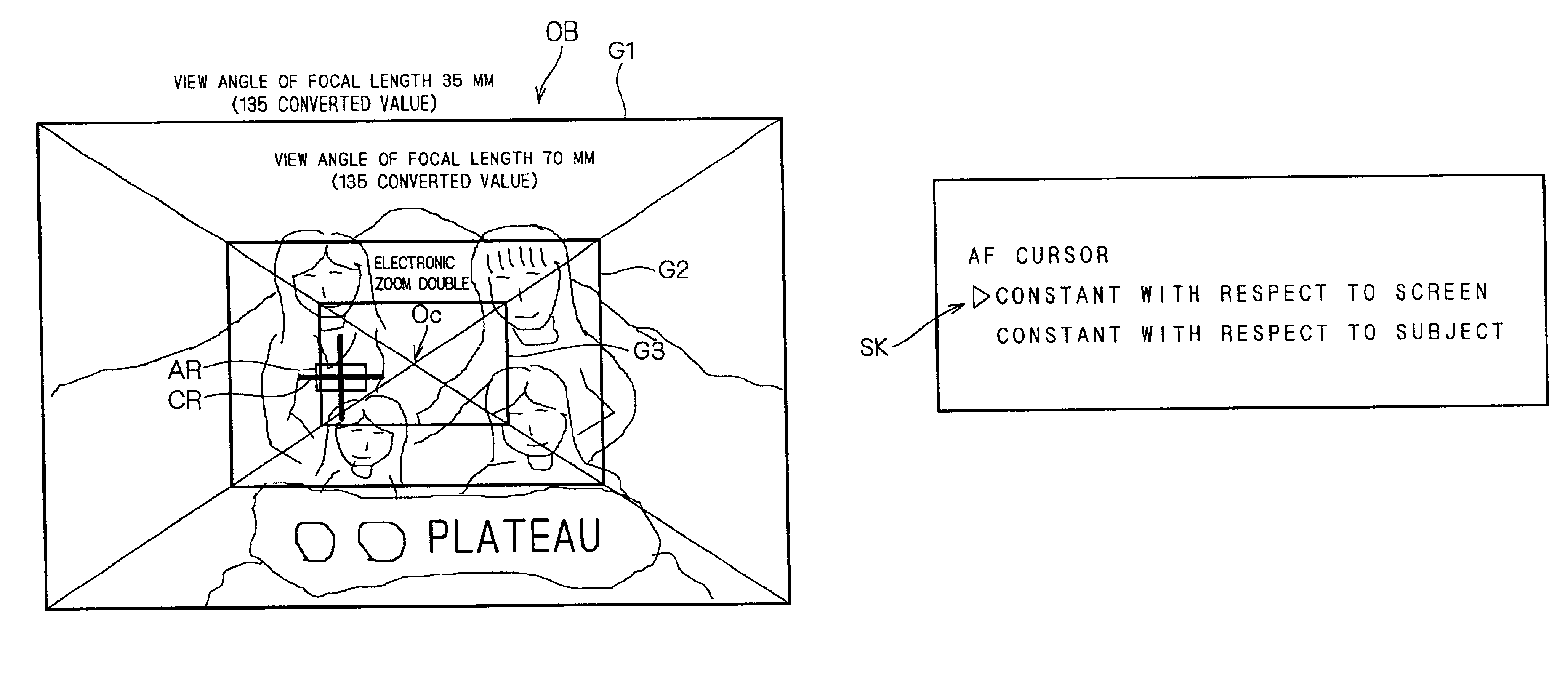
24 is a drawing that explains an enlarged screen display;

[0038]FIG. 25 is a drawing that explains an enlarged screen display;

[0039]FIG. 26 is a drawing that explains an enlarged screen display;

[0040]FIG. 27 is a drawing that explains a n enlarged screen display;

[0041]FIG. 28 is a drawing that shows a selected screen with respect to AF cursor;

[0042]FIG. 29 is a drawing that explains operations of a digital camera in accordance with a second preferred embodiment of the present invention;

[0043]FIG. 30 is a drawing that explains an operation of the digital camera;

[0044]FIG. 31 is a drawing that explains an operation of the digital camera;

[0045]FIG. 32 is a drawing that explains an LCD screen when zoomed;

[0046]FIG. 33 is a drawing that explains an LCD screen when zoomed;

[0047]FIG. 34 is a drawing that explains an LCD screen when zoomed; and

[0048]FIG. 35 is a drawing that explains an LCD screen when zoomed.

DESCRIPTION OF THE PREFERRED EMBODIMENTS

[0049][First Preferred Embodiment]

[0050]

[00...


PUM


Abstract

On a screen G1 of a liquid crystal display, a digital camera displays an AF cursor for use as a focusing point. Thus, a shooter shifts the AF cursor to the portion of a subject to be focused, so as to carry out the setting. Here, when the subject is zoomed up to an enlarged screen G2 through an optical zooming operation, the AF cursor is displayed on the enlarged screen G2, following the subject. Moreover, in the case when the subject is electronically zoomed up to an enlarged screen G3, the AF cursor is also displayed on the enlarged screen G3, following the subject. Thus, even when a zooming process is carried out, it is not necessary to adjust the position of the AF cursor; thus, it becomes possible to improve the operability of the digital camera.

Description

[0002]This application is based on application No. 2001-3698 filed in Japan, the contents of which are hereby incorporated by reference.BACKGROUND OF THE INVENTION[0003]1. Field of the Invention[0004]The present invention relates to a digital camera wherein a focusing point, etc. can be specified.[0005]2. Description of the Background Art[0006]In conventional digital camera techniques, Japanese Patent Application Laid-Open No. 3-187580 / 1991 has disclosed techniques in which the shooter can desirably set AF and AE points with respect to a subject so as to prevent a centered blanking image and problems with an image taken with mixed subjects located closely and far apart from the camera.[0007]However, the above-mentioned camera is applicable to the case in which a mono-focal point lens is used; however, in the case when it is applied to the case in which a zooming operation is carried out by a zoom lens or the case in which an electronic zooming operation is carried out, the relations...

Claims


Application Information

Patent Timeline
Patent Type & Authority Patents(United States)
IPC IPC(8): H04N5/232G02B7/28G03B7/08G03B7/28G03B13/36G03B17/20G03B19/02H04N23/40
CPCH04N5/23212H04N5/23296H04N5/23293H04N23/675H04N23/673H04N23/633H04N23/69
Inventor FUJII, SHINICHITANAKA, TOSHIYUKINIIKAWA, MASAHITO
Owner MINOLTA CO LTD
Learn More