Charge control circuit for a micro-electromechanical device

a micro-electromechanical and control circuit technology, applied in static indicating devices, variable capacitors, instruments, etc., can solve the problems of increasing capacitance, reducing the range of motion, and increasing the voltage controlling the electrodes

Inactive Publication Date: 2005-02-08
HEWLETT PACKARD DEV CO LP
View PDF15 Cites 31 Cited by
  • Summary
  • Abstract
  • Description
  • Claims
  • Application Information

AI Technical Summary

Benefits of technology

The present invention provides a circuit that controls a device with a variable capacitance. It uses a charge storage device to balance the charge between it and the device, ensuring they are both at the same voltage. This results in a more stable and reliable operation of the device.

Problems solved by technology

Technological Problem: Miniature Electromagnetic Systems (MES), particularly those that require precise movements like Optically Display System (OVD). These MES rely heavily on small gaps between their moving parts called elec troads. However, these miniaturized electronic elements also experience potential issues caused by static electricity or energy transferring through other materials. To solve this problem, there has been proposed various methods involving creation of films made up of different material layers separated by insulating spacers.

Method used


Image

  • Charge control circuit for a micro-electromechanical device
  • Charge control circuit for a micro-electromechanical device
  • Charge control circuit for a micro-electromechanical device

Examples


Embodiment Construction

In the following detailed description of the preferred embodiments, reference is made to the accompanying drawings which form a part hereof, and in which is shown by way of illustration specific embodiments in which the invention may be practiced. It is to be understood that other embodiments may be utilized and structural or logical changes may be made without departing from the scope of the present invention. The following detailed description, therefore, is not to be taken in a limiting sense, and the scope of the present invention is defined by the appended claims.

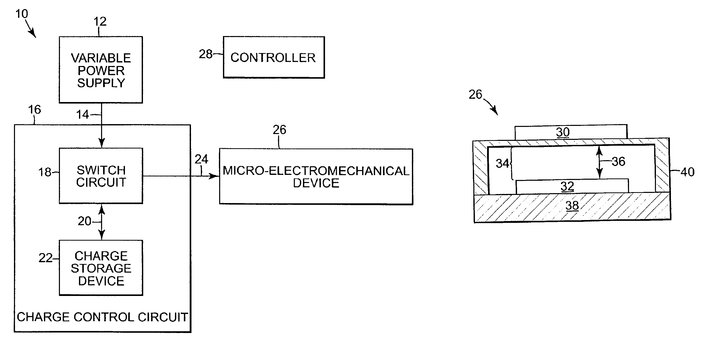
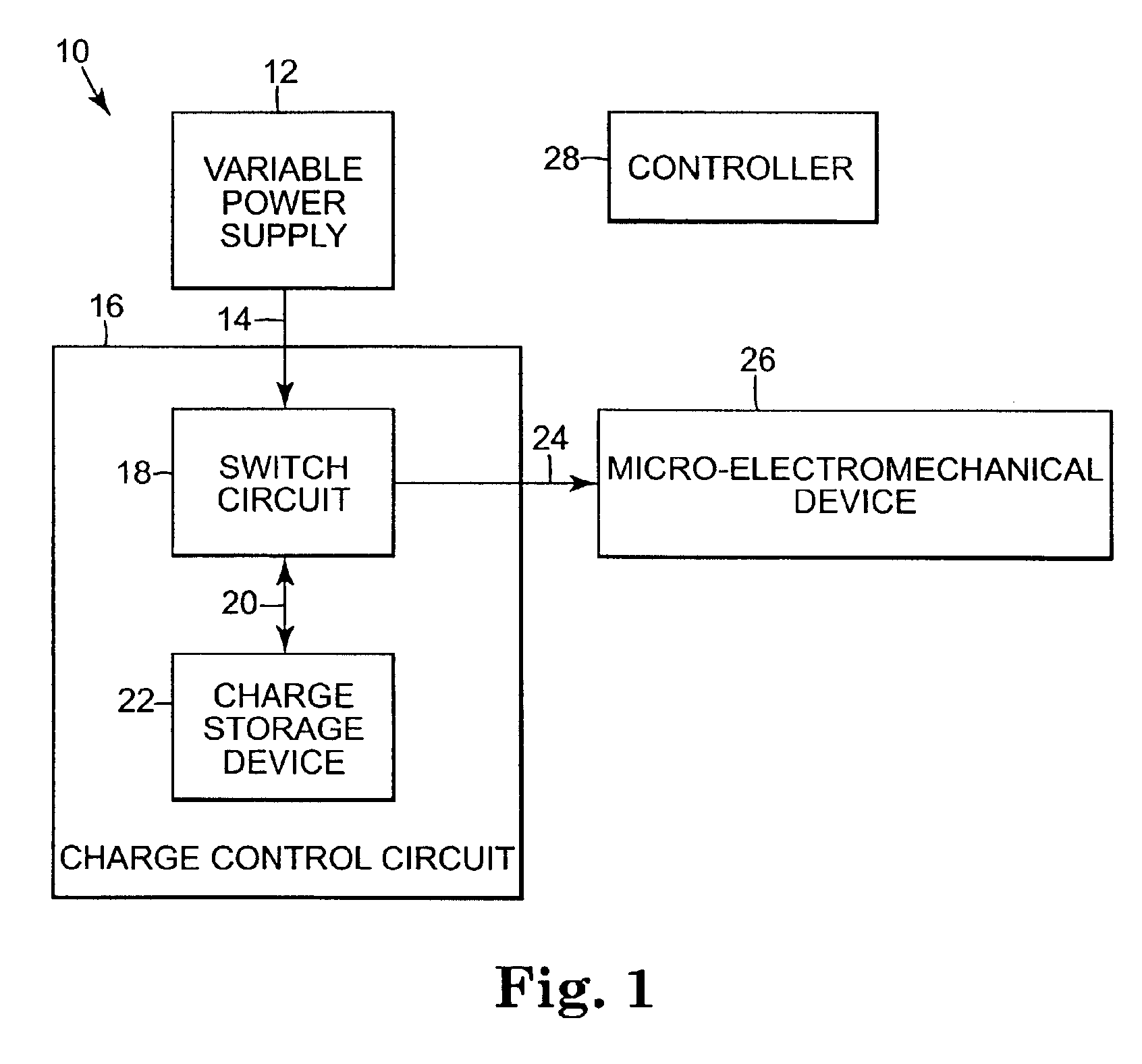
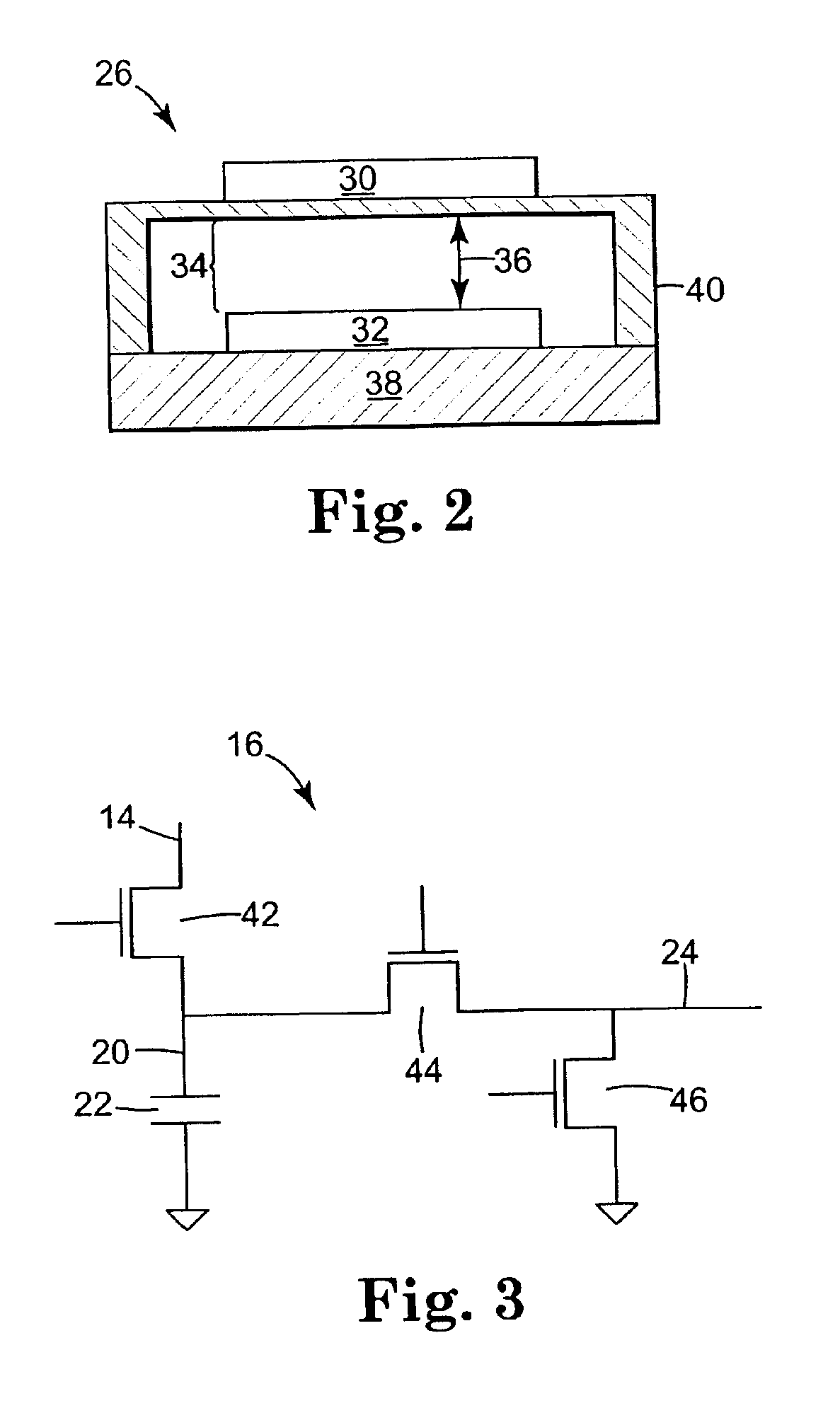
FIG. 1 is a diagram illustrating an exemplary embodiment of a micro-electromechanical system 10 according to the present invention. The micro-electromechanical system 10 includes a variable power supply 12, a charge control circuit 16, a micro-electromechanical device 26 and a controller 28. In the exemplary embodiment, charge control circuit 16 includes a switch circuit 18 and a charge storage device 22. In the exempl...


PUM


Abstract

A charge control circuit for controlling a micro-electromechanical device having a variable capacitance is disclosed. In one embodiment, a charge storage device is configured to store a charge amount. A switch circuit is configured to control the variable capacitance of the micro-electromechanical device by sharing the charge amount between the charge storage device and the micro-electromechanical device to equalize the charge storage device and the micro-electromechanical device to a same voltage.

Description


Claims


Application Information

Patent Timeline
Owner HEWLETT PACKARD DEV CO LP
Why Eureka
Try Eureka