
Method and apparatus for performing technology mapping

a technology mapping and technology technology, applied in the field of technology mapping methods and apparatuses, can solve the problems of specific algorithms that are not suitable for the optimization of more general circuits, limited application of two-level minimization,

Inactive Publication Date: 2005-02-08
CADENCE DESIGN SYST INC
View PDF52 Cites 13 Cited by
  • Summary
  • Abstract
  • Description
  • Claims
  • Application Information

AI Technical Summary

Benefits of technology

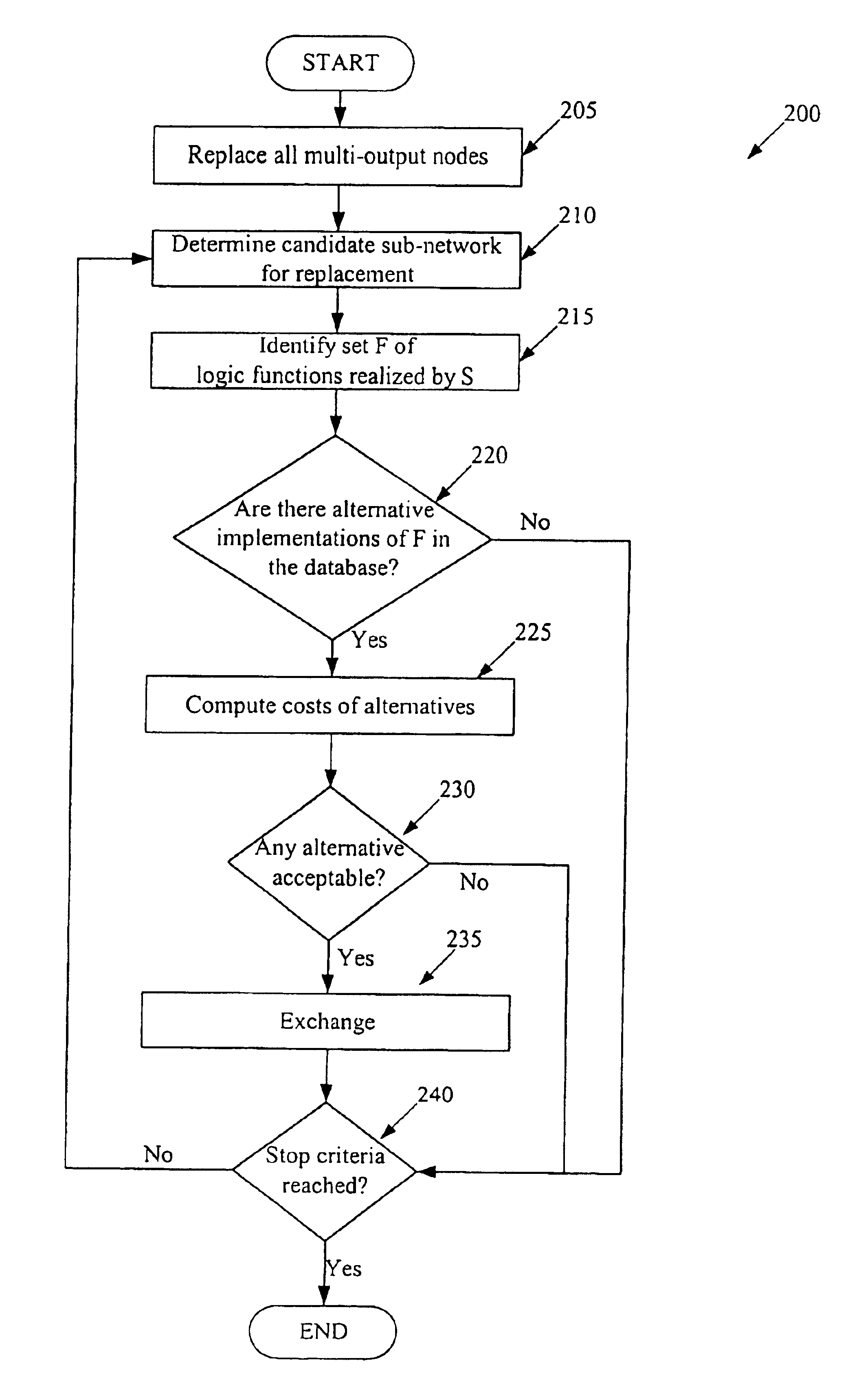
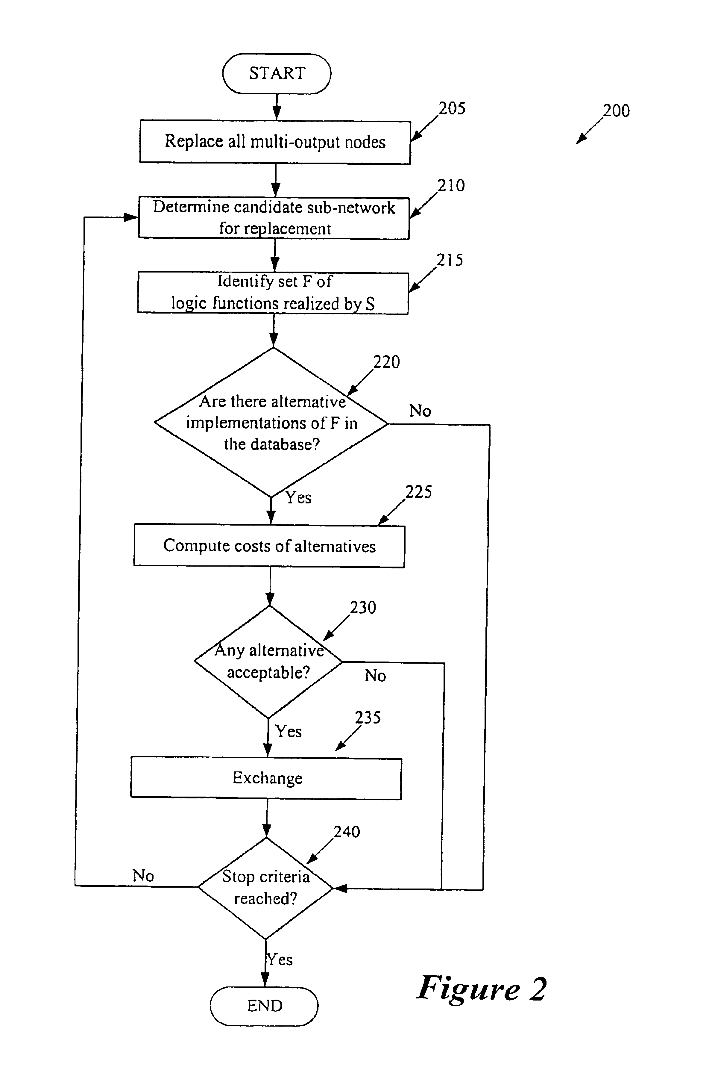
Some embodiments of the invention provide a method for pre-tabulating sub-networks. This method (1) generates a sub-network that performs a function, (2) generates a parameter based on this function, and (3) stores the sub-network in a storage structure based on the generated parameter. In some embodiments, the generated sub-network has several circuit elements. Also, in some embodiments, the generated sub-network performs a set of two or more functions. The generated parameter is an

Problems solved by technology

The application of two-level minimization is limited, though, because only simple logic functions can be represented efficiently in that form.
These are highly specific algorithms that are not suitable for the optimization of more general circuits.

Method used


Image

  • Method and apparatus for performing technology mapping
  • Method and apparatus for performing technology mapping
  • Method and apparatus for performing technology mapping

Examples


Embodiment Construction

In the following description, numerous details are set forth for purpose of explanation. However, one of ordinary skill in the art will realize that the invention may be practiced without the use of these specific details. In other instances, well-known structures and devices are shown in block diagram form in order not to obscure the description of the invention with unnecessary detail.

I. Terminology.

The definitions of several terms in this document are provided below.

IC region refers to the entire IC or a portion (or block) of the IC.

Logical description of a design refers to the logical representation of the design. Examples of logical description include an RTL description (e.g., a Verilog, VHDL, HDL, or BLIFF description), a combinational-logic expression (e.g., a Boolean expression), etc. Circuit description of a design refers to the circuit representation of the design. Examples of circuit description include technology-level designs (also called bound circuit networks), inter...


PUM


Abstract

Some embodiments of the invention provide a method for pre-tabulating sub-networks. This method (1) generates a sub-network that performs a function, (2) generates a parameter based on this function, and (3) stores the sub-network in a storage structure based on the generated parameter. In some embodiments, the generated sub-network has several circuit elements. Also, in some embodiments, the generated sub-network performs a set of two or more functions. Some embodiments store each generated sub-network in an encoded manner. Some embodiments provide a method for producing a circuit description of a design. This method (1) selects a candidate sub-network from the design, (2) identifies an output function performed by the sub-network, (3) based on the identified output function, identifies a replacement sub-network from a storage structure that stores replacement sub-networks, and (4) replaces the selected candidate sub-network with the identified replacement sub-network in certain conditions. In some embodiments, this method is performed to map a design to a particular technology library. Some embodiments provide a data storage structure that stores a plurality of sub-networks based on parameters derived from the output functions of the sub-networks.

Description

FIELD OF THE INVENTIONThe present invention is directed towards method and apparatus for performing technology mapping.BACKGROUND OF THE INVENTIONA combinational logic synthesizer produces an efficient circuit description for a specific region of an integrated circuit (“IC”). The IC region can be the entire IC or a portion (i.e., a block) of the IC. An IC or IC block typically performs a set of Boolean combinational-logic functions F that depend on a set of Boolean variables X. The Boolean function set F typically includes several functions f—1, . . . , f_m, and the Boolean variable set X typically includes several variables X—1, . . . , X_n.In terms of the IC design, the variable set X includes inputs of the IC region. Also, the outputs of some or all Boolean functions f_i serve as the outputs of the IC region. In addition, each function f_i specifies a logic operation that needs to be performed on one or more inputs to the function. The output of each Boolean function f_i(X) can b...

Claims


Application Information

Patent Timeline
IPC IPC(8): G06F17/50
CPCG06F17/505G06F30/327
Inventor TEIG, STEVENHETZEL, ASMUS
Owner CADENCE DESIGN SYST INC
Learn More