Above ground container stabilizer

a stabilizer and container technology, applied in the field of plant support structures, can solve the problems of affecting the stability of the above ground container, the deformation of the wire structure, and the inability to perform both functions of the structure, etc., and achieves the effect of stable plant support, easy adjustment, and stable plant suppor

Inactive Publication Date: 2005-02-15
CHEROKEE MFG LLC
View PDF14 Cites 12 Cited by
  • Summary
  • Abstract
  • Description
  • Claims
  • Application Information

AI Technical Summary

Benefits of technology

The upper oval is easily adjusted to receive differing sized containers by manually increasing or decreasing the upper oval diameter. Additionally, the present invention provides a more stable plant support since each the lower oval can be easily adjusted by either manually increasing of decreasing the lower oval diameter. This eliminates the negative affect of rigid connections on the upper and lower ovals. Elimination of the rigid connections on the plant support prolongs the operational life of the support and minimizes breaks and fractures in the device.
In an alternative embodiment of the present invention, additional vertical portions or legs are provided to provide additional support and stability.

Problems solved by technology

Most structures, however, do not perform both functions.
The wire structures frequently deform, or, even worse, the welds holding the wire structure together break and fracture due to formation of rust.
Weld and fastener locations are where rust typically first occurs in the wire structures, which damages the structural integrity and operating life of the structure.
Moreover, the rigid attachments of many support structures prevent adjustment of its shape and will fracture when the wire structure is manipulated or assembled and disassembled.
Prior support structures are lightweight which makes them susceptible to being blown over in inclement weather or knocked over by a person passing by.
Additionally, prior plant supports have experienced problems due to their shape and structural orientation.
For example, many plant supports have insufficient space to accommodate various sized plant containers.
A new support structure must be purchased to accommodate the larger pot since the prior support structure cannot be adjusted to accommodate the larger pot.
Having structurally limited support structures increases the cost of equipment for a user, and, increases the chances of losing a structure when not in use.
Finally, the shape of some plant supports is disadvantageous to stacking a multiple of plant supports on top of one another.

Method used


Image

  • Above ground container stabilizer
  • Above ground container stabilizer
  • Above ground container stabilizer

Examples


Embodiment Construction

Various embodiments of the present invention are shown and described to support plant containers. It is to be understood that though these embodiments are shown and described in isolation, various features of each embodiment can be combined with the others to produce a variety of embodiments.

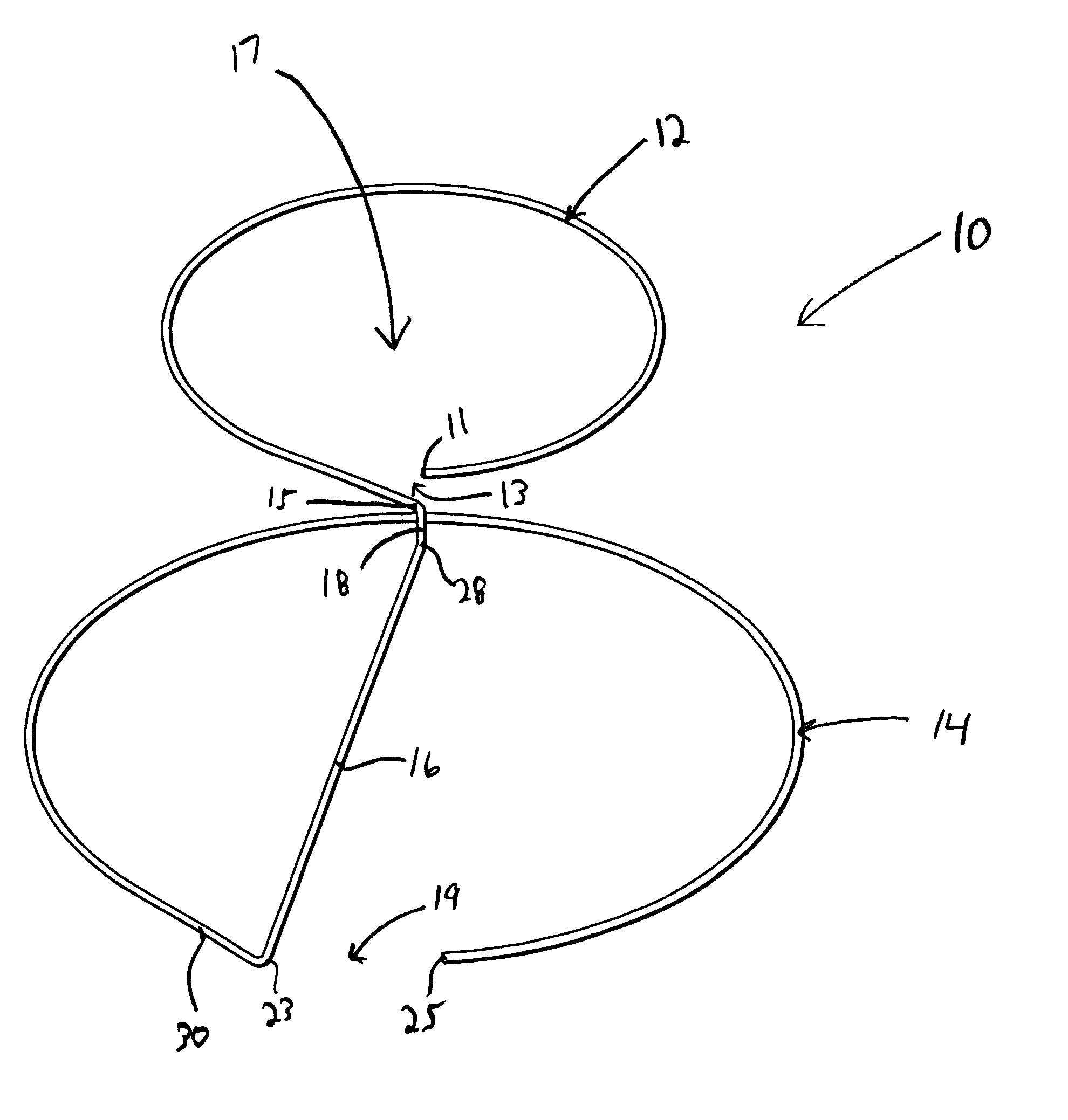
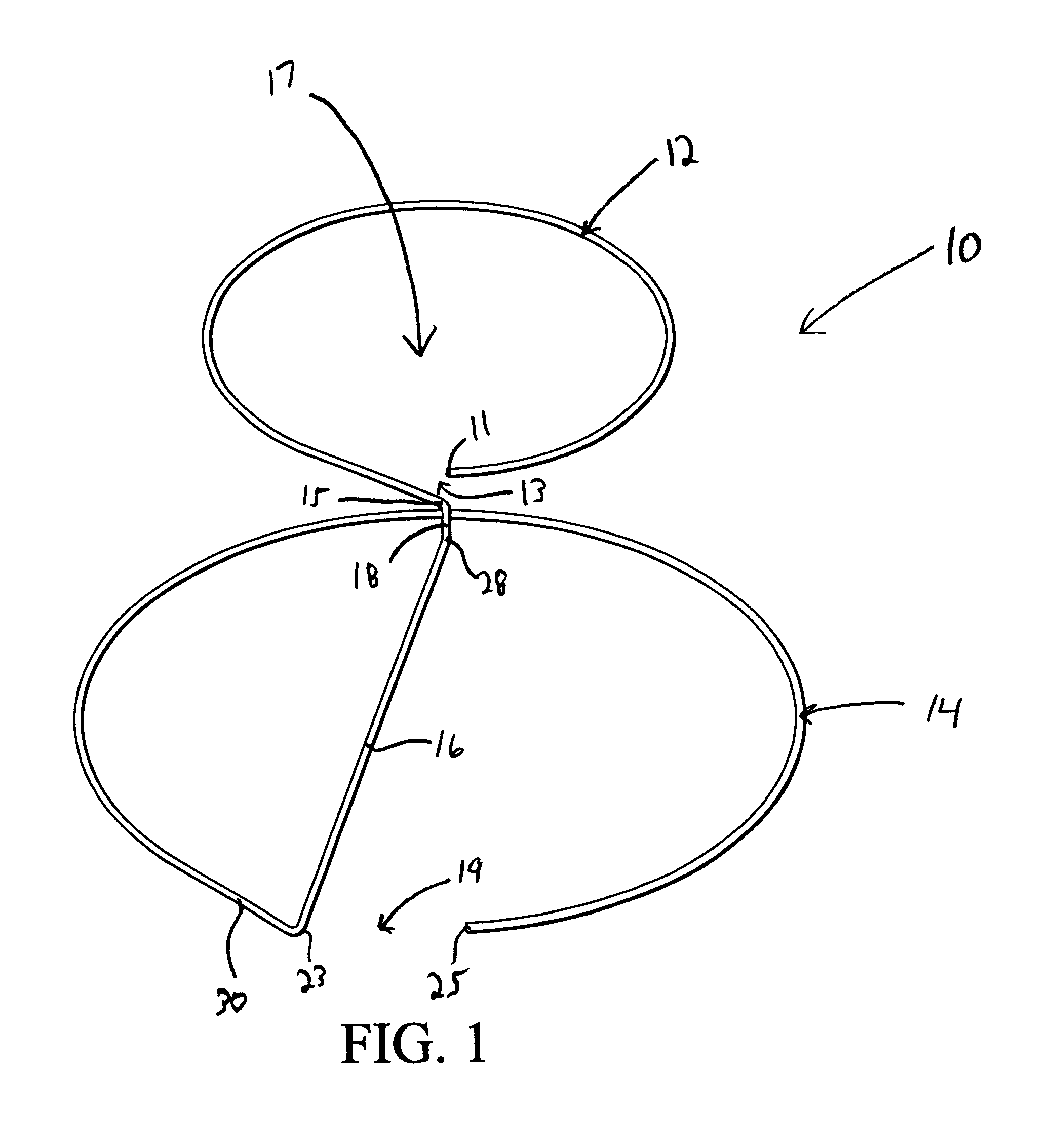
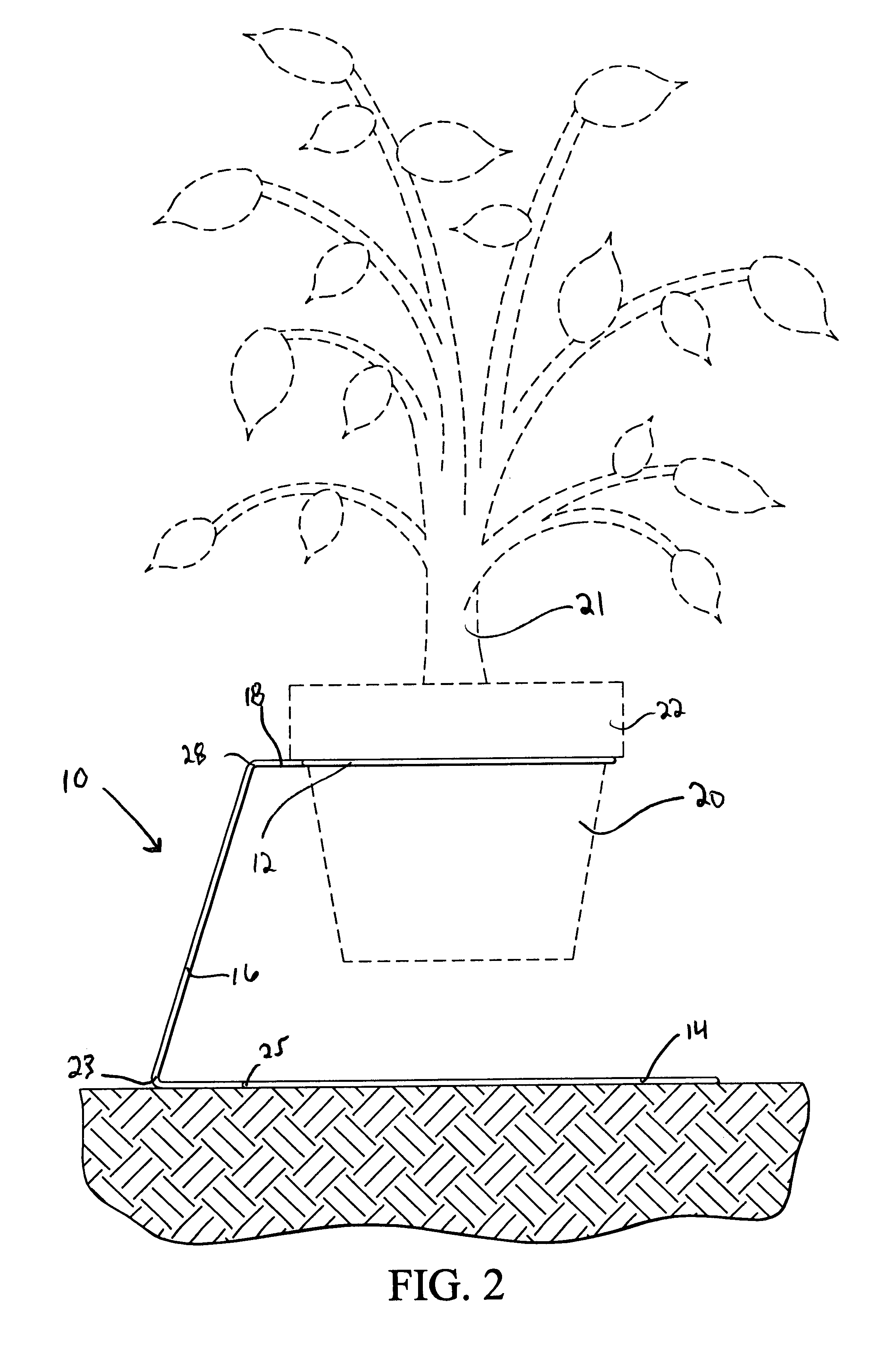
Referring to FIGS. 1-4, a first embodiment of a wire plant support is shown and generally referred to as 10. The plant support a unitary elongate member constructed of a single continuous wire having plurality of bends formed at predetermined locations to define an upper oval portion 12, a lower oval portion 14 and a vertical portion 16 extending between the upper oval and lower oval. Vertical portion 16 positions the upper oval 12 and the lower oval 14 in a substantially parallel, vertically spaced, horizontally disposed orientation such that the upper oval 12 and lower oval 14 are centered about a vertical axis. The upper oval 12 and lower oval 14 define an interior volume 17 that is adapted t...


PUM


Abstract

A unitary elongated member comprises bends at predetermined locations to form an upper ring and a lower ring. A vertical portion connecting the upper ring to the lower ring, orienting the upper and lower rings in a parallel, vertically spaced, horizontally disposed orientation such that the upper and lower rings are centered about a vertical axis. The lower ring has a larger diameter than the upper ring and is adapted rest on the ground or a floor. The elongated member is rigid yet sufficiently malleable to be manipulated by a user to be adjusted to support various sized plant containers. The elongated unitary member may be made of galvanized wire or plastic material resistant to rust. The rings are shaped so as to define an inner volume of the plant support to accommodate the insertion of a plant container housing a plant. The plant container is adapted rest on the upper ring so as to position the plant container above the ground. The upper ring is easily adjusted to receive differing sized containers by manually increasing or decreasing the upper ring diameter. Additionally, the present invention provides a more stable plant support since each the lower ring can be easily adjusted by either manually increasing of decreasing the lower ring diameter. In an alternative embodiment of the present invention, additional vertical portions or legs are provided to provide additional support and stability.

Description

FIELD OF THE INVENTIONThis invention relates generally to plant support structures. More particularly the present invention relates to an inexpensive multi-purpose structure that operates as a support for plants residing in containers.BACKGROUND OF THE INVENTIONMany different devices are used to help plants through their different stages of development. Some plant species grow to be quite tall and have long branches and vines. To prevent these plants from dying, they must be supported and protected to minimize damage from harsh handling and environmental conditions.In the culturing and development of potted plants or plants resident in a container, many times a stand or support is used to position the potted plant on the ground or floor a in predetermined orientation. The users of stands, such as gardeners and nursery operators, use the stands to prevent toppling of the plant due to wind or inadvertent bumping. Additionally, the stands facilitate moving of plants and optimize the us...

Claims


Application Information

Patent Timeline
Patent Type & Authority Patents(United States)
IPC IPC(8): A47G7/00A47G7/02
CPCA47G7/025
Inventor GUNDERMAN, JOHN E.
Owner CHEROKEE MFG LLC
Why Eureka
Try Eureka