Electromechanical cylinder lock-key-combination

a technology of electronic cylinders and lock keys, applied in the field of electronic cylinder lock key combination, can solve the problems of not being able to affect or reach the special locking disc through the key channel, breaking the additional locking mechanism,

Inactive Publication Date: 2005-02-15
ABLOY OY
View PDF8 Cites 21 Cited by
  • Summary
  • Abstract
  • Description
  • Claims
  • Application Information

AI Technical Summary

Benefits of technology

The solution is simple and does not require members movable in the axial direction of the lock, but only turning movement

Problems solved by technology

Since it is then not possible to affect the coupling member and the special locking disc directly with the key, it is not possible either, in case of an incorrect electron

Method used


Image

  • Electromechanical cylinder lock-key-combination
  • Electromechanical cylinder lock-key-combination
  • Electromechanical cylinder lock-key-combination

Examples


Embodiment Construction

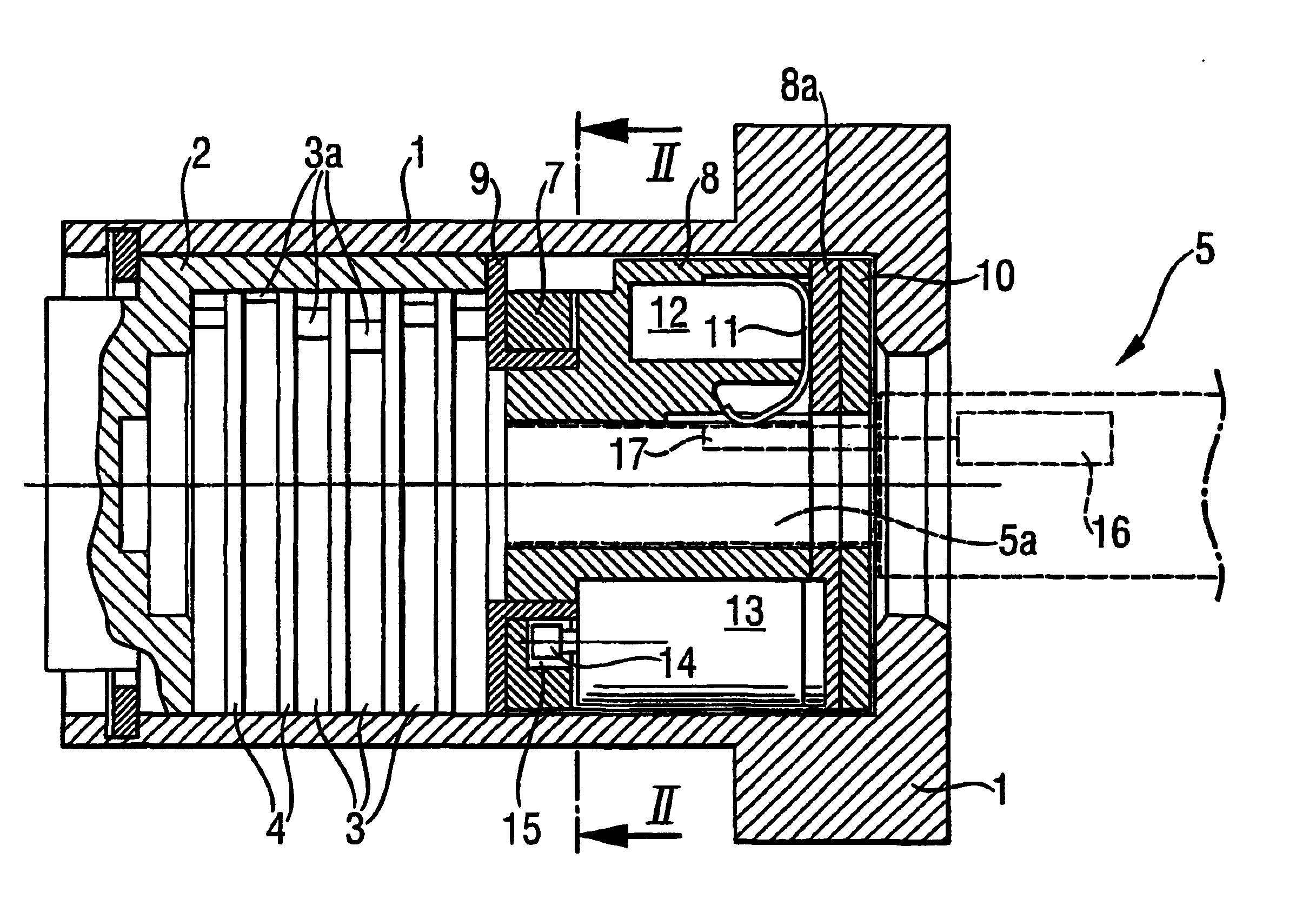
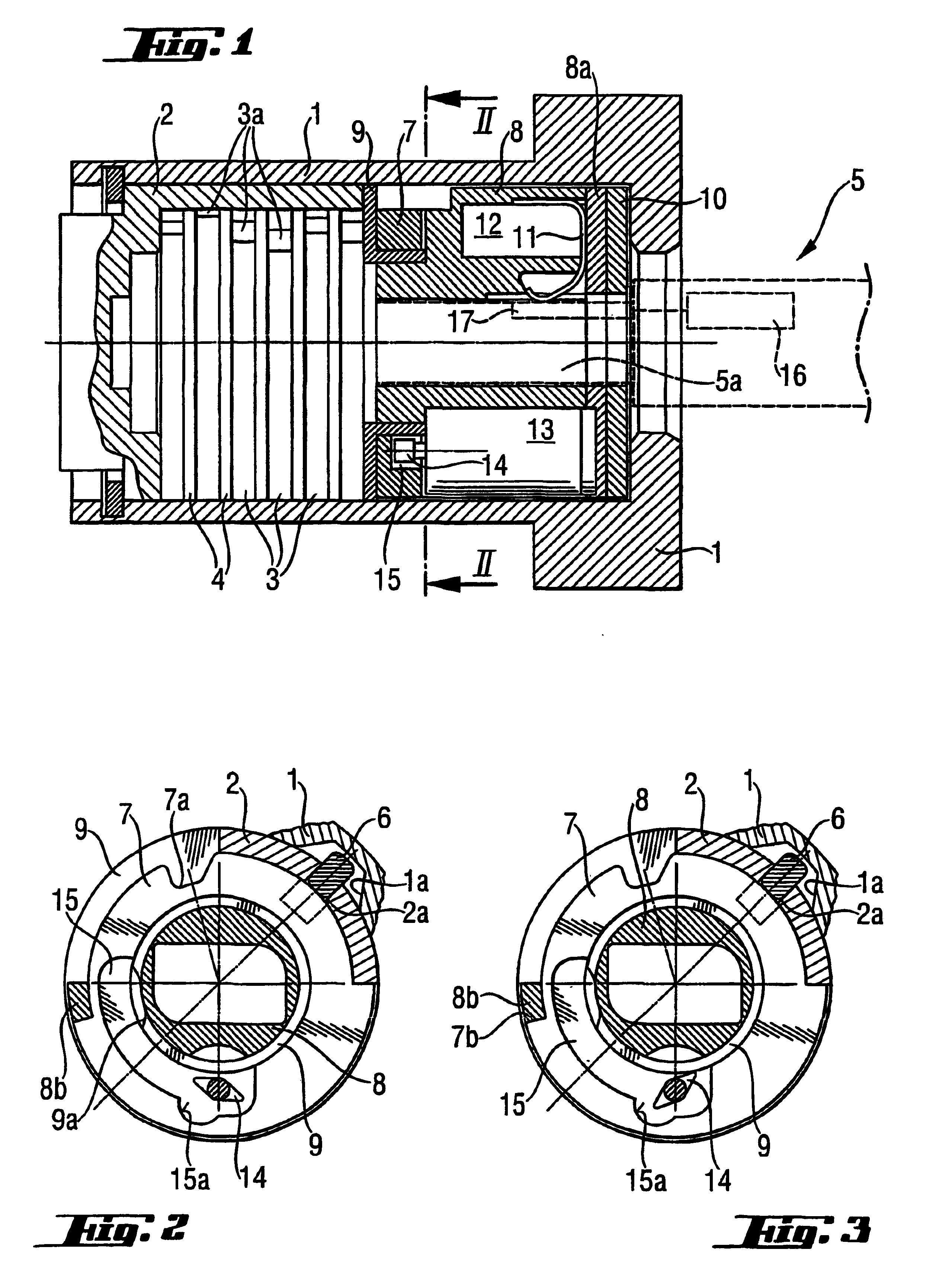
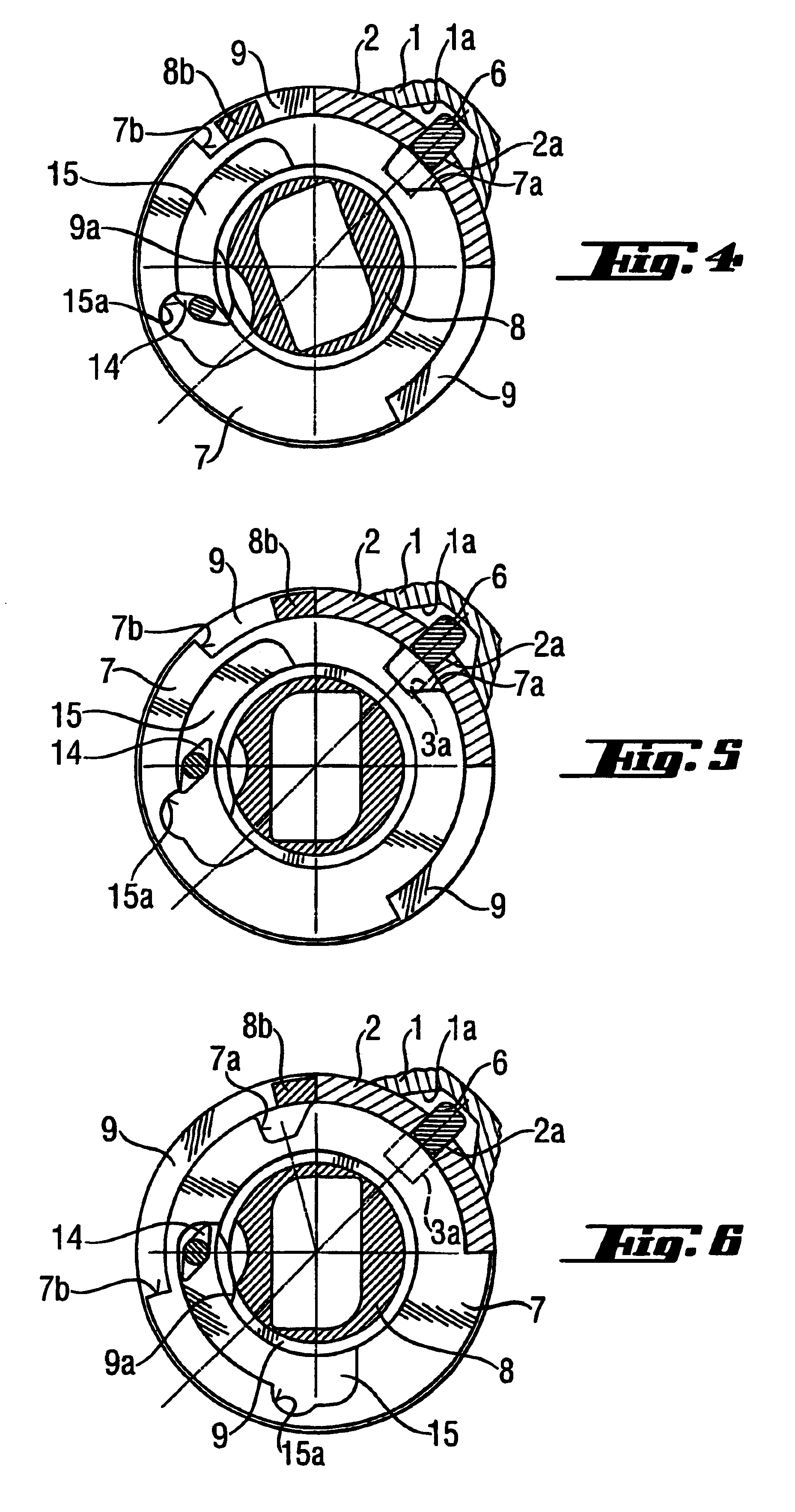
In the drawings reference numeral 1 designates a lock body enclosing a lock cylinder 2 and a locking bar 6 which, in its locking position, is located partly in a groove 1a in an inner surface of the lock body 1 and partly in a slot 2a in the lock cylinder 2. In the locking position of the locking bar 6 turning of the lock cylinder 2 relative to the lock body 1 is prevented. Positioned inside the lock cylinder 2 is a set of discs which includes a number of locking discs 3, each provided with a peripheral notch 3a, and intermediate discs 4 separating the locking discs. The locking discs 3 can be turned in a manner known as such by utilising a “mechanical code” formed in a shank 5a of a key 5, the “mechanical code” being provided by combination surfaces cut in the key shank and which are not shown in detail in the drawings. The key 5 is thus able to turn the locking discs into a position opening the lock, in which the peripheral notches 3a are arranged at the position of the slot 2a of...


PUM


Abstract

An electromechanical cylinder lock-key-combination includes a key having a mechanical locking code and a device for storing an electronic code and sending it into the lock. A lock body encloses a turnable lock cylinder and a locking mechanism which normally prevents turning of the lock cylinder with regard to the lock body and which can be moved by the key into a releasing position allowing turning of the lock cylinder. The lock includes a special locking disc with which the key is not in direct mechanical force transmission connection, an identification and control device for receiving and identifying the electronic code from the key, and an electric operating device with a turnable coupling member attached thereto and having a free position and a coupling position in which it couples the special locking disc with the turning movement of the key for opening the lock, whereby when there is a match with the correct electronic code of the key the identification and control device activates the electric operating device to guide the coupling member to its coupling position. The coupling member is located and is in cooperation with a guiding groove in the special locking disc, the guiding groove having a guiding surface which the coupling member affects in its coupling position thereby turning the special locking disc when the key is turned in the lock.

Description

BACKGROUND OF THE INVENTIONThe invention relates to an electromechanical cylinder lock-key-combination.In order to improve the security of locks there has been a shift from mechanical cylinder locks to electromechanical cylinder locks which have locking means which can be opened mechanically directly with the key of the lock or electronically by means of an electronic code supplied separately from a key or the like storing means. Numerous solutions are known in which the correct electronic code is arranged to influence a separate blocking means and either move it directly into a position releasing the lock cylinder or enable it to be moved into such a releasing position.An alternative known type of electromechanical cylinder lock has conventional locking means and, in addition thereto, further locking means which cannot normally be operated by means of a mechanical key of the lock but which, as a consequence of a correct electronic code, can be separately coupled to become in force ...

Claims


Application Information

Patent Timeline
IPC IPC(8): E05B47/06E05B21/06E05B21/00E05B29/00E05B47/00E05B29/04
CPCE05B47/0653E05B21/066E05B47/0002Y10T70/7102Y10T70/7949Y10T70/7633Y10T70/7079
Inventor HURSKAINEN, OIVASIVONEN, HANNU
Owner ABLOY OY
Why Eureka
Try Eureka