Electrically driven brake device and control apparatus thereof

a technology of brake device and control apparatus, which is applied in the direction of braking system, braking components, transportation and packaging, etc., can solve the problems of inability to secure sufficient braking force from time to time, inability to supply electric power to all the brake actuators, and inability to solve the problem of insufficient braking force, etc., to achieve high reliability, high reliability, and high reliability

Inactive Publication Date: 2005-02-15
HITACHI LTD
View PDF14 Cites 14 Cited by
  • Summary
  • Abstract
  • Description
  • Claims
  • Application Information

AI Technical Summary

Benefits of technology

According to one aspect of the present invention, an electrically driven brake device includes a power breaker capable of insulating and separating a plurality of brake actuators into two systems. Since the power source system in which abnormality develops can thus be insulated and separated from the normal power source system, the present invention can accomplish an electrically driven brake device having high reliability, and also a control apparatus of the brake device.
According to the second aspect of the present invention, an electrically driven brake device includes a plurality of power supply sources and a power breaker capable of insulating and separating a plurality of brake actuators into two separate systems. Therefore, even when any abnormality develops, the power source system in which such abnormality occurs can be separated, and the power source system to which at least one of the power supply sources is connected is left, and an electrically driven brake device having higher reliability can be accomplished.
According to the third aspect of the present invention, an electrically driven brake device includes a cutoff switch for separating a power source line into a first power source line and a second power source line, a first voltage detection circuit for detecting a voltage of the first power source line, and a second voltage detection circuit for detecting a voltage of the second power source line, wherein the second power source line supplies driving power to the first voltage detection circuit and the first power source line supplies driving power to the second voltage detection circuit. Even when abnormality develops in the power source line, therefore, the cutoff switch cuts off the power source line and driving power is supplied from the power source line on the normal side to the voltage detection circuit that detects the voltage of the power source line on the abnormal side. Consequently, voltage detection can be continued. Because the cutoff state can be released as

Problems solved by technology

In the conventional brake device described above, however, electric power cannot be supplied to all the brake actuators when any abnormality develops in a relay unit that switches the main battery and the auxiliary battery, and sufficient braking force cann

Method used


Image

  • Electrically driven brake device and control apparatus thereof
  • Electrically driven brake device and control apparatus thereof
  • Electrically driven brake device and control apparatus thereof

Examples


first embodiment

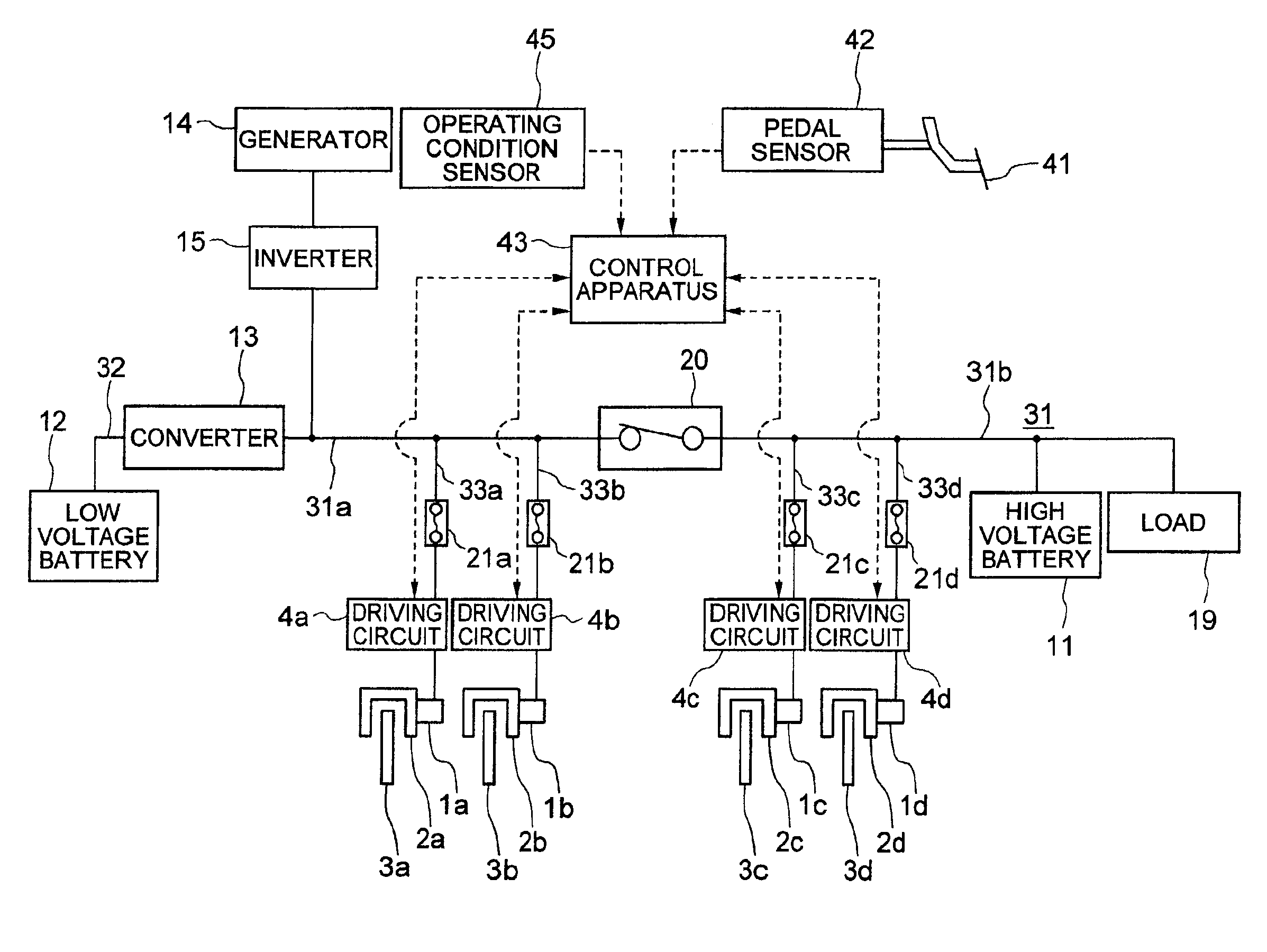
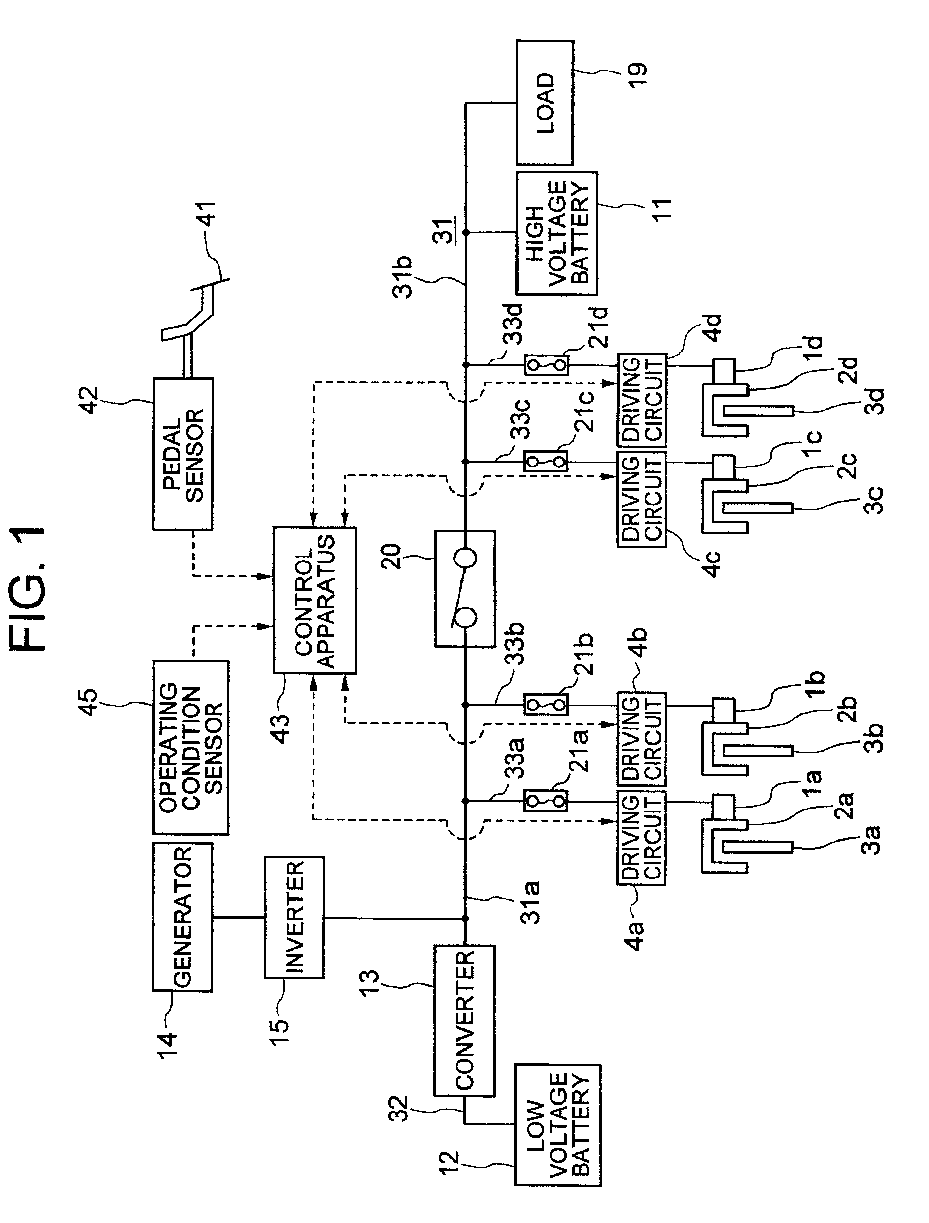
FIG. 1 is a system structural view of the electrically driven brake device according to the present invention.

The electrically driven brake device according to this embodiment includes a control apparatus 43. The control apparatus 43 is an electronic controller for controlling braking force of a vehicle, that includes a microcomputer, a memory for storing a control program and data and an input / output circuit for controlling input / output of signals to and from outside.

The electrically driven brake device includes disk rotors 3a, 3b, 3c and 3d. (Reference numerals each having a suffix will be hereinafter represented by suffixes a to d). The disk rotor 3a rotates with a right front wheel and the disk rotor 3b, with a left front wheel. The disk rotor 3c rotates with a right rear wheel and the disk rotor 3d, with a left rear wheel. Alternatively, the disk rotor 3a rotates with the right front wheel, the disk rotor 3b, with the left rear wheel, the disk rotor 3c with the left front wheel...


PUM


Abstract

An electrically driven brake device includes a plurality of brake actuators for generating braking force when driven electrically, a power supply source for storing electric energy and supplying power to the brake actuators, a power source line for connecting the power supply source and the brake actuators, and a power breaker at a position of the power source line at which the brake actuators can be insulated and separated into at least two systems.

Description

BACKGROUND OF THE INVENTIONThis invention relates to an electrically driven brake device to be mounted to a vehicle, which brake device generates braking force by using power supplied from a power supply source.An electrically driven brake device that operates electric motors by electric power and electric signals and generates braking force is known in the past. The electrically driven brake device proposed in JP-A-11-171006, for example, includes brake actuators that generate braking force when driven electrically. This brake device can generate suitable braking force in accordance with a depression quantity of a brake pedal. The brake actuator of this device includes a main battery and an auxiliary battery as power supply sources, and uses the auxiliary battery as the power supply source when the main battery is consumed. Consequently, the brake device can always exhibit braking force characteristics having excellent response.SUMMARY OF THE INVENTIONTo reliably acquire braking fo...

Claims


Application Information

Patent Timeline
IPC IPC(8): B60T8/88B60T13/74B60T8/34B60T17/22B60T13/00B60T8/32B60T17/18
CPCB60T8/3255B60T8/343B60T17/221B60T13/74B60T8/88
Inventor YOKOYAMA, ATSUSHINISHIGAITO, TAKAOMIKADOMUKAI, YUZOICHINOSE, MASANORIMATSUBARA, KENICHIROUEKI, NOBUYUKIMANAKA, TOSHIO
Owner HITACHI LTD
Why Eureka
Try Eureka