Rapid response electronic clinical thermometer

a technology of electronic clinical thermometers and thermometers, which is applied in the field of clinical thermometers, can solve the problems of large heat capacity of above conventional clinical thermometers and the use of expensive components in these thermometers, and achieve the effect of reducing the temperature measurement time and rapid indication of accurate temperatur

Inactive Publication Date: 2005-02-15
ACTHERM INC
View PDF24 Cites 142 Cited by
  • Summary
  • Abstract
  • Description
  • Claims
  • Application Information

AI Technical Summary

Benefits of technology

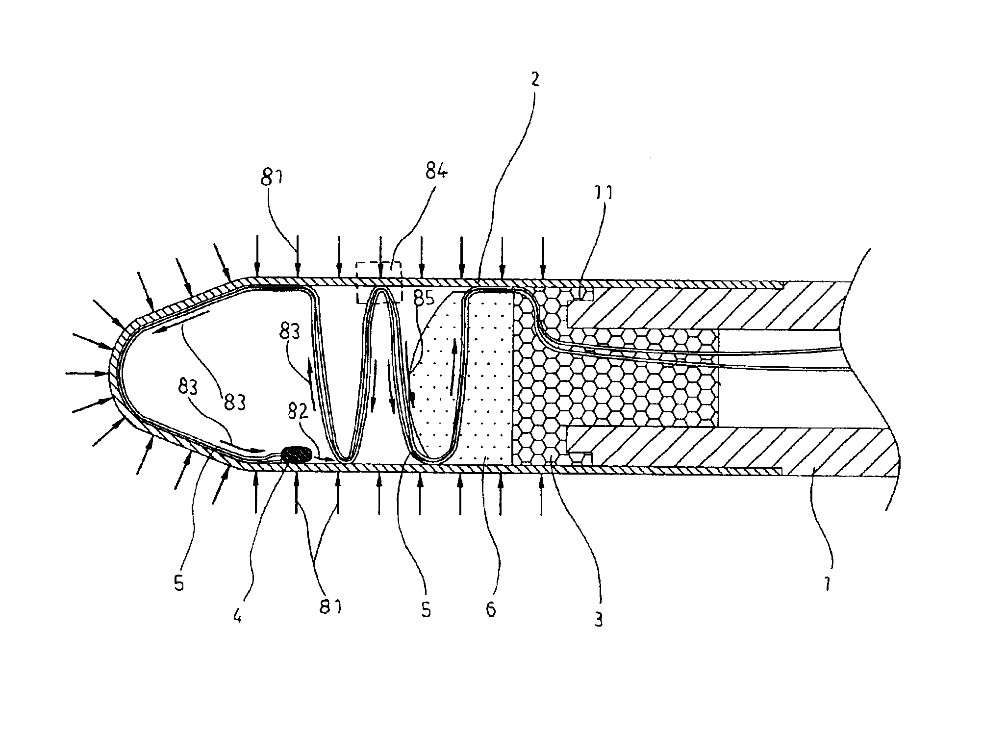
Accordingly, it is an object of the present invention to provide a rapid respond electronic clinical thermometer having a measuring end portion being adhered with a metal head portion having a temperature sensing element and a conductive wire joining the temperature sensing element, characterized in that the conductive wire is adhered to the inner wall of the metal head portion such that the conductive wire is not a heat dissipation portion for heat energy surrounding the sensing element, and further acts as a source of heat energy compensation so as to rapidly indicate the accurate temperature, reducing the temperature measuring time.

Problems solved by technology

However, a number of expensive components are employed in these thermometers.
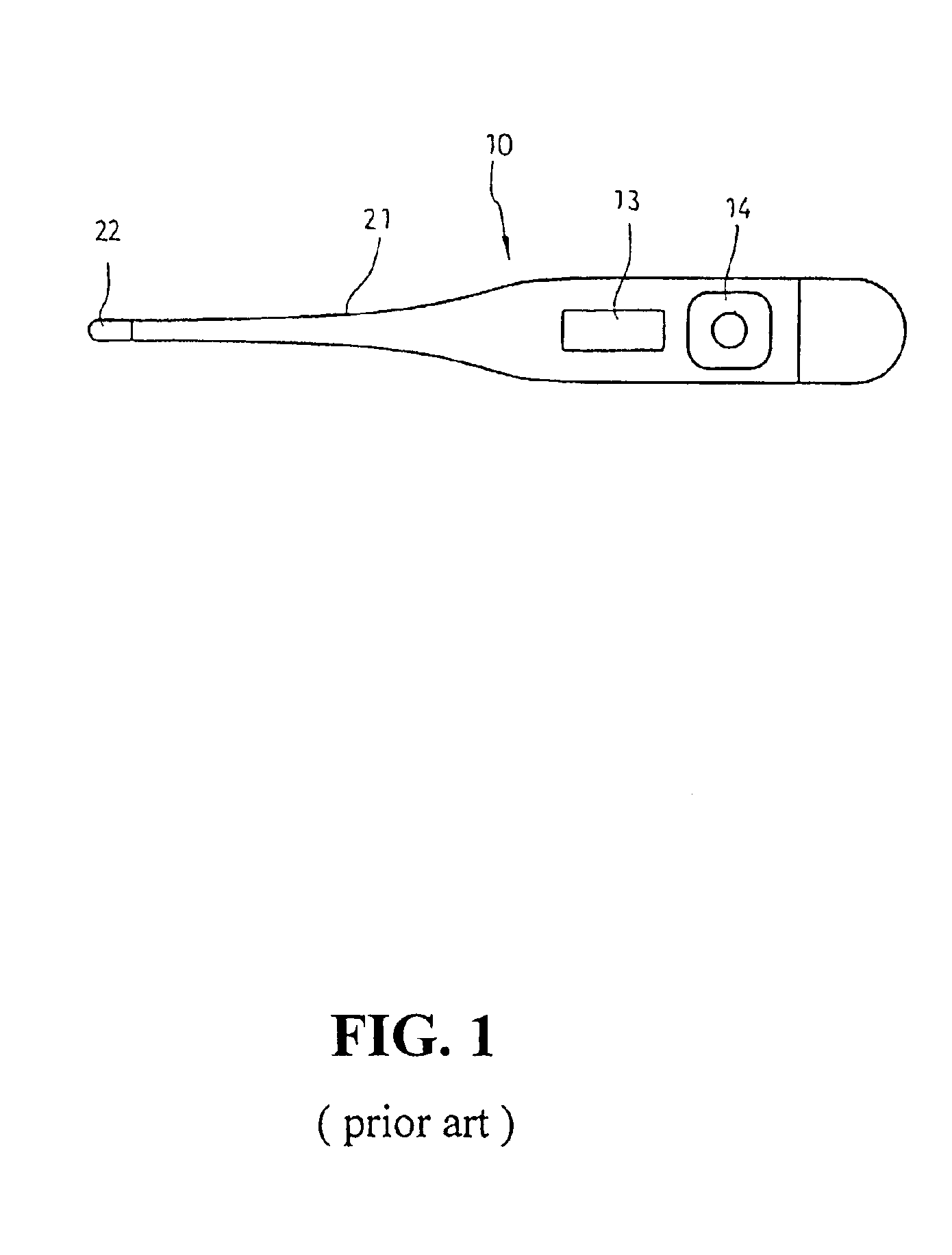
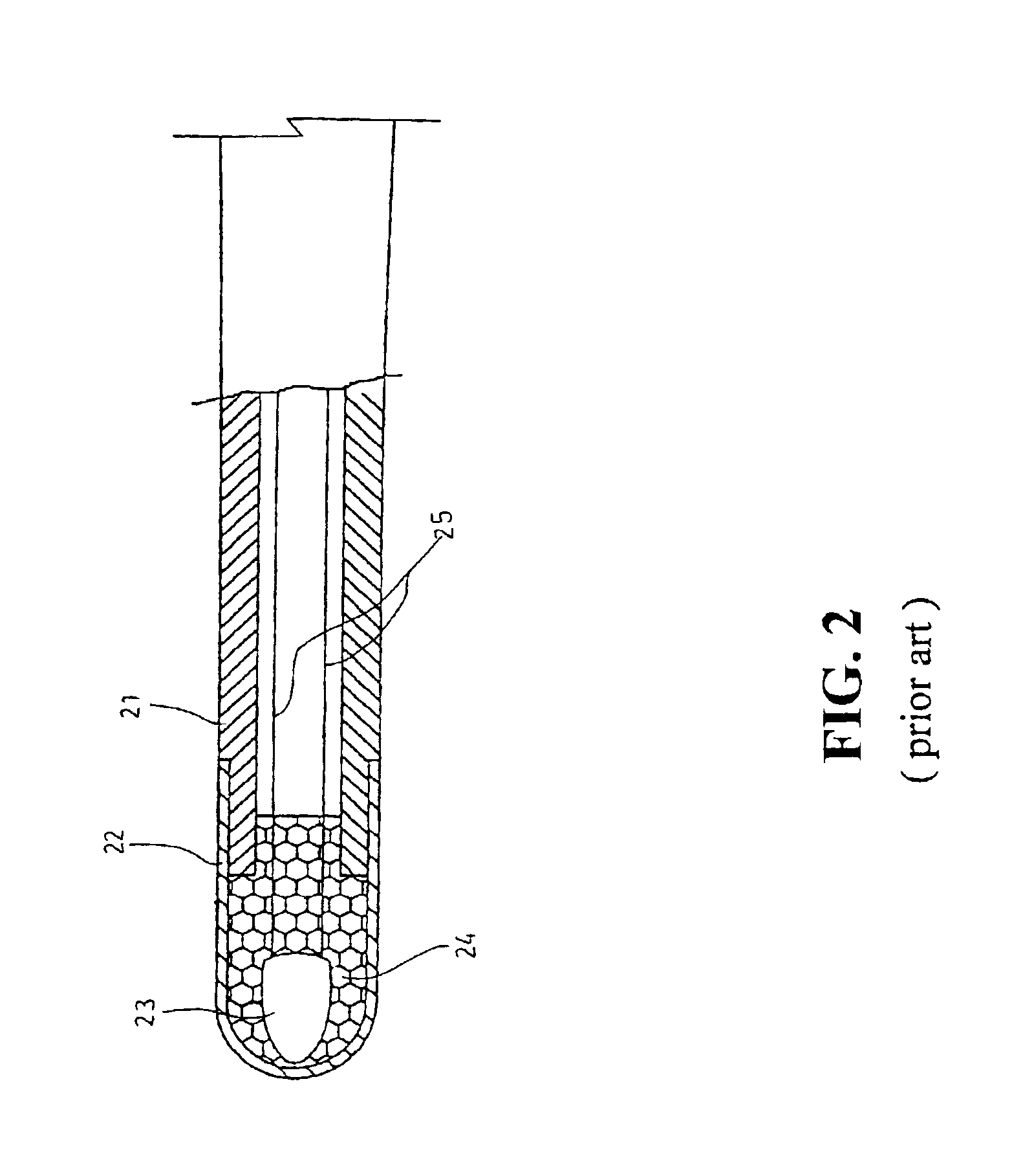
The above conventional clinical thermometer has the drawback of large heat capacity.

Method used


Image

  • Rapid response electronic clinical thermometer
  • Rapid response electronic clinical thermometer
  • Rapid response electronic clinical thermometer

Examples


Embodiment Construction

The following descriptions are of exemplary embodiments only, and are not intended to limit the scope, applicability or configuration of the invention in any way. Rather, the following description provides a convenient illustration for implementing exemplary embodiments of the invention. Various changes to the described embodiments may be made in the function and arrangement of the elements described without departing from the scope of the invention as set forth in the appended claims.

Referring to FIGS. 8 and 9, there is shown a clinical thermometers having a measuring end 1 with an end portion connected to a metal head portion 2. The measuring end 1 and the metal head portion 2 can be mounted with an adhesive agent. A stepped recess 11 is provided at the external side of the stepped portion and the recess 11 and the metal head portion 2 are adhered and secured with an adhesion agent 3, which is waterproof.

A temperature sensing element 4 is provided at the interior of the metal head...


PUM

PropertyMeasurementUnit
lengthaaaaaaaaaa
timeaaaaaaaaaa
lengthaaaaaaaaaa

Abstract

A rapid response electronic clinical thermometer is disclosed. The clinical thermometer comprises a measuring end portion adhered to a metal head portion having a temperature sensing element and a conductive wire joining the temperature sensing element, characterized in that the conductive wire is adhered to the inner wall of the metal head portion such that the conductive wire is not a heat dissipation portion for heat energy surrounding the sensing element, and further acts as a source of heat energy compensation so as to indicate the accurate temperature, reducing the temperature measuring time.

Description

BACKGROUND OF THE INVENTION1. Technical Field of the InventionThe present invention relates to a clinical thermometer, and in particular, an electronic thermometer having a measuring end portion being adhered with a metal head portion having a temperature sensing element and a conductive wire joining the temperature sensing element, with the conductive wire being adhered to the inner wall of the metal head portion such that the conductive wire is not a heat dissipation portion for heat energy surrounding the sensing element, and the conductive wire further acts as a source of heat energy compensation so as to rapidly indicate the accurate temperature, reducing the time required for measuring temperature.2. Description of the Prior ArtNormally, a conventional electronic clinical thermometer takes a long time to measure body temperature and it was only during 1980-1990, that rapid respond electronic clinical thermometers became utilized. However, a number of expensive components are e...

Claims


Application Information

Patent Timeline
Patent Type & Authority Patents(United States)
IPC IPC(8): G01K13/00A61B5/01
CPCG01K13/002G01K13/20
Inventor CHEN, MING-YUN
Owner ACTHERM INC
Why Eureka
Try Eureka