

Mop assembly and cart
a technology of mop and assembly, which is applied in the direction of cleaning machines, carpet cleaners, hand devices, etc., can solve the problems of difficult clean up situations, affecting the operation of the liquid delivery system on the mop, and the valve to become sticky or even plugged, so as to achieve quick and easy change
- Summary
- Abstract
- Description
- Claims
- Application Information
AI Technical Summary
Benefits of technology
Problems solved by technology
Method used
Image

Examples
Embodiment Construction
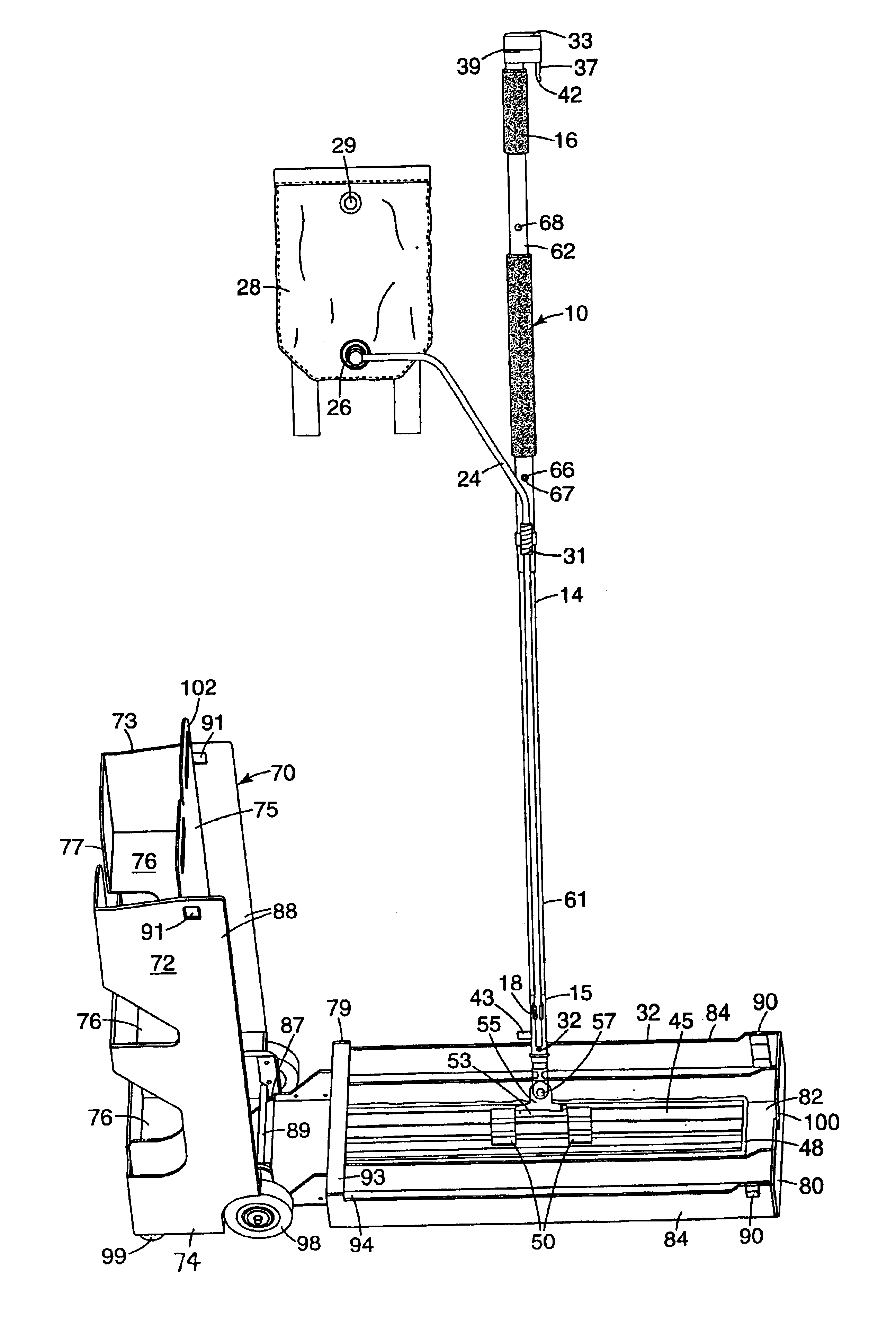
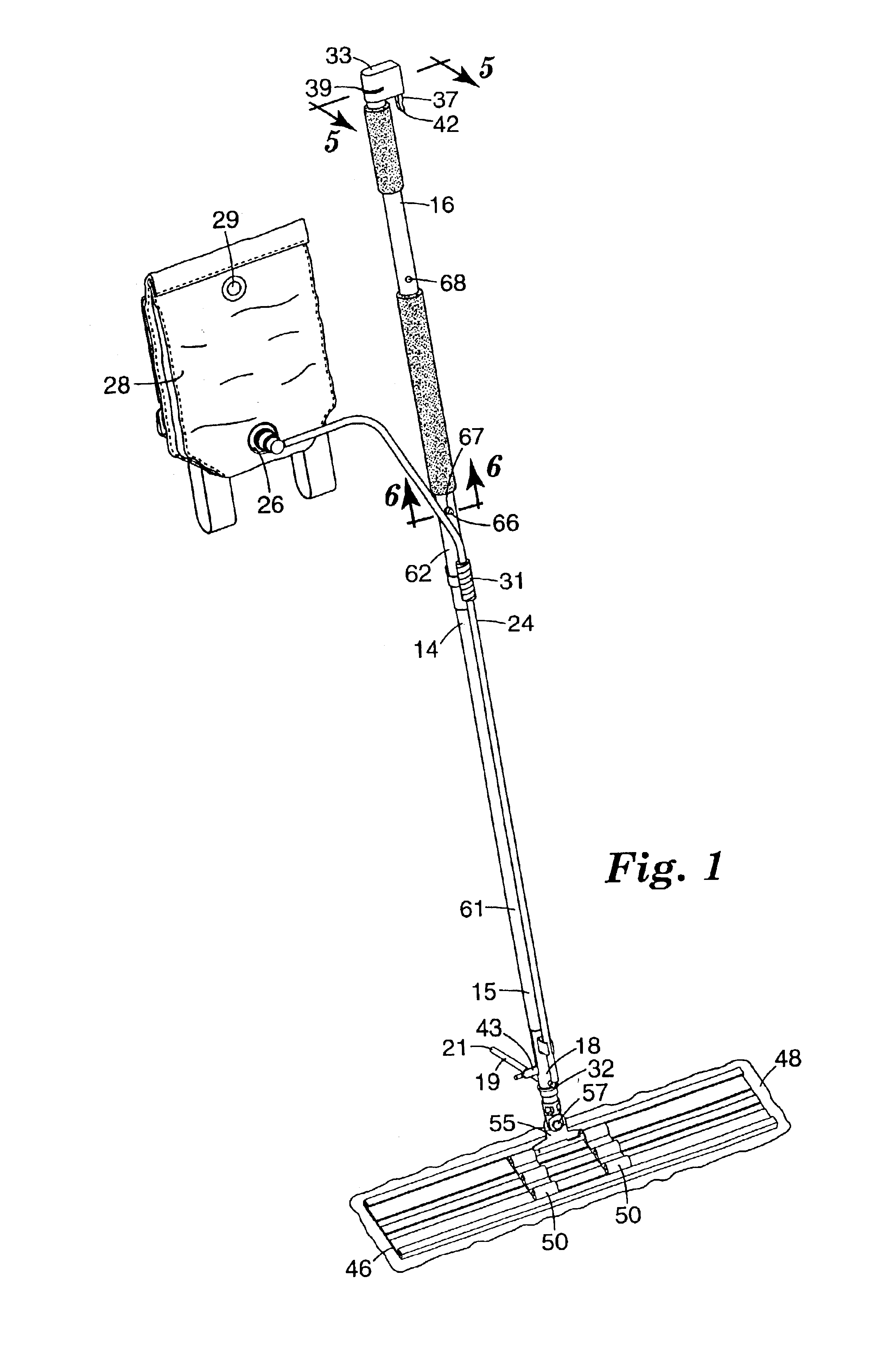
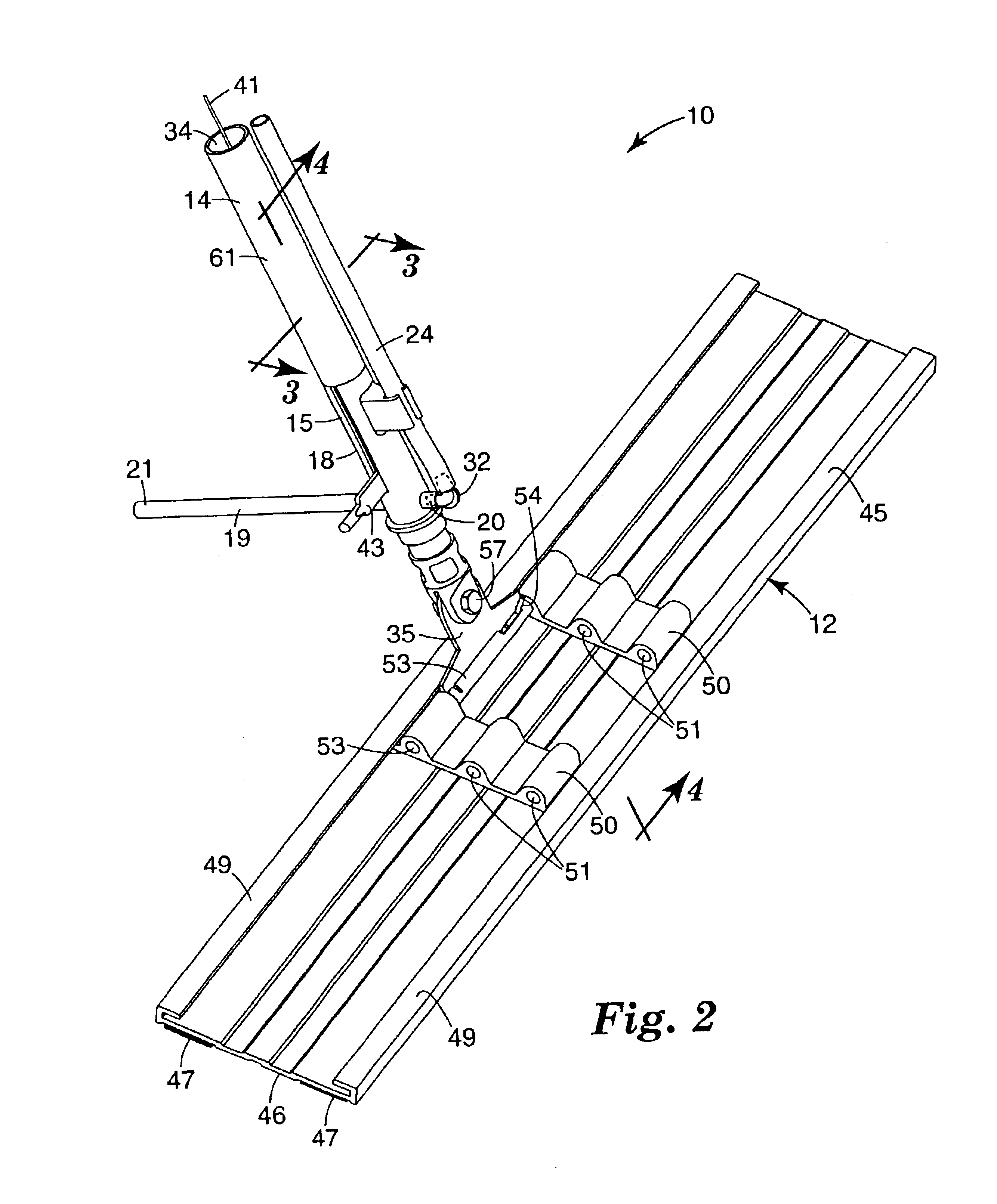
Referring now to FIGS. 1 through 4 of the drawing there is illustrated a mop assembly 10 according to the present invention that can be used for applying liquid (e.g., floor coatings, floor cleaners, floor sealers, floor finishes, disinfectants, etc.) to a surface such as the surface of a floor.
The mop assembly 10 comprises a mop head 12, an elongate handle 14 having a first end 15 pivotally attached to the mop head 12, and a portion adjacent an opposite second end 16 that is adapted to be manually engaged to move the mop head 12 along the surface. A valve assembly 18 mounted on the handle 14 adjacent its first end 15 has inlet and outlet openings at and provided by opposite ends 20 and 21 of a length 19 of resiliently flexible elastic tubing (e.g., {fraction (5 / 16)} O.D. latex tubing) included in the valve assembly 18 that has a portion extending transversely through the handle 14. The valve assembly also includes first and second members 22 and 23 in the handle 14 on opposite side...
PUM
 Abstract
Description
Claims
Application Information