Method for adding an apparent non-signal line to a lateral flow assay
Inactive Publication Date: 2005-02-15
QUIDEL
View PDF31 Cites 130 Cited by
Summary
Abstract
Description
Claims
Application Information
AI Technical Summary
This helps you quickly interpret patents by identifying the three key elements:
Problems solved by technology
Method used
Benefits of technology
Benefits of technology
a positive sample flow. A further advantage of the present invention is the avoidance of a line that is substantially visible before the sample is added
Problems solved by technology
Single-step devices obviate the necessity of performing complicated and time consuming processing steps that may introduce errors in the end result.
A portion of the chromatographic medium is removed, or otherwise partially blocked, thereby affecting the flow path of the liquid.
Such devices are limited as the test strips may present a line that is visible before the sample is added.
Previous methods are further disadvantaged as the additional manufacturing step involves a difficult placement proc
Method used
Image
Click on the blue label to locate the original text in one second.
Reading with bidirectional positioning of images and text.
Examples
example 1
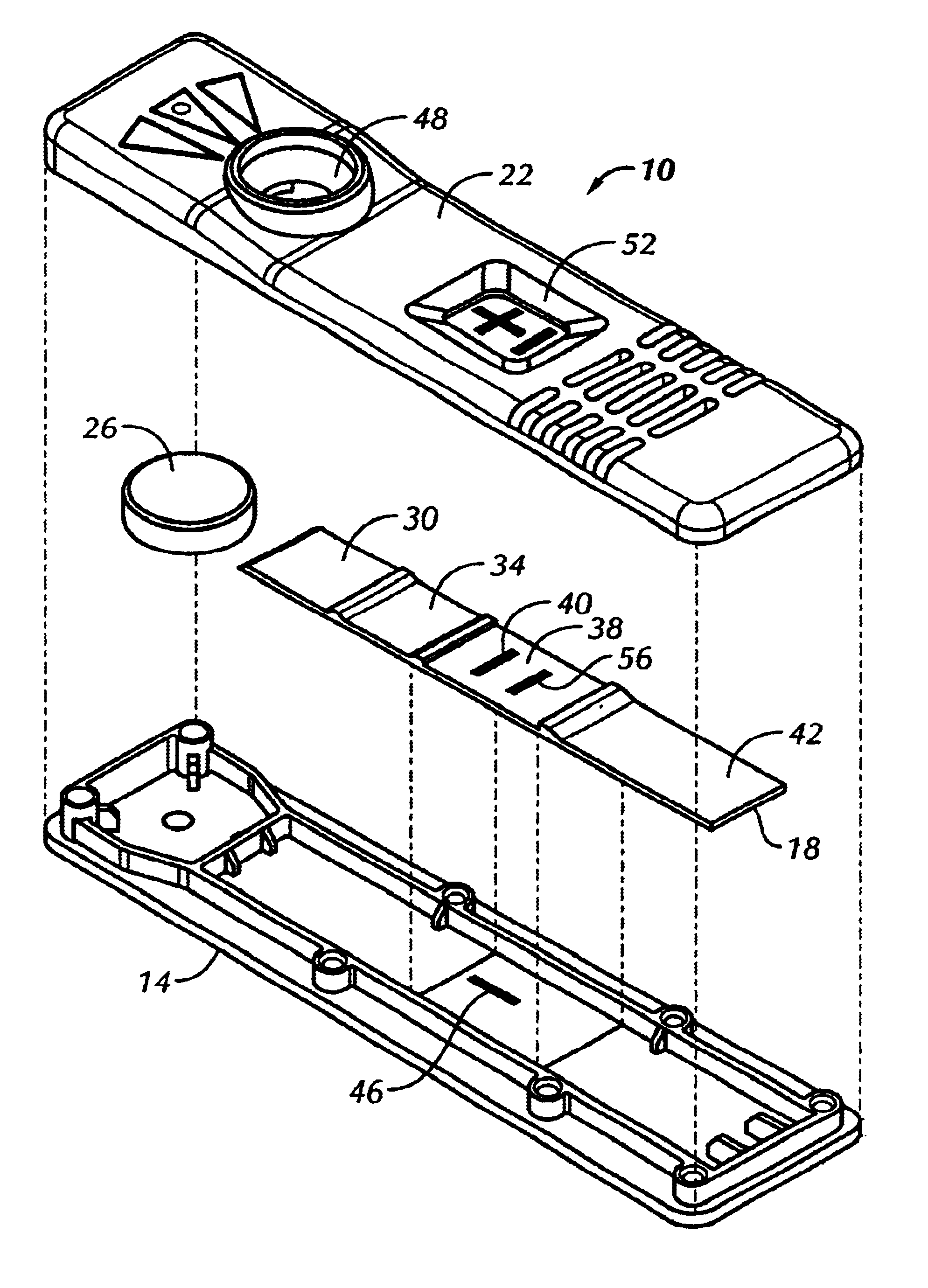
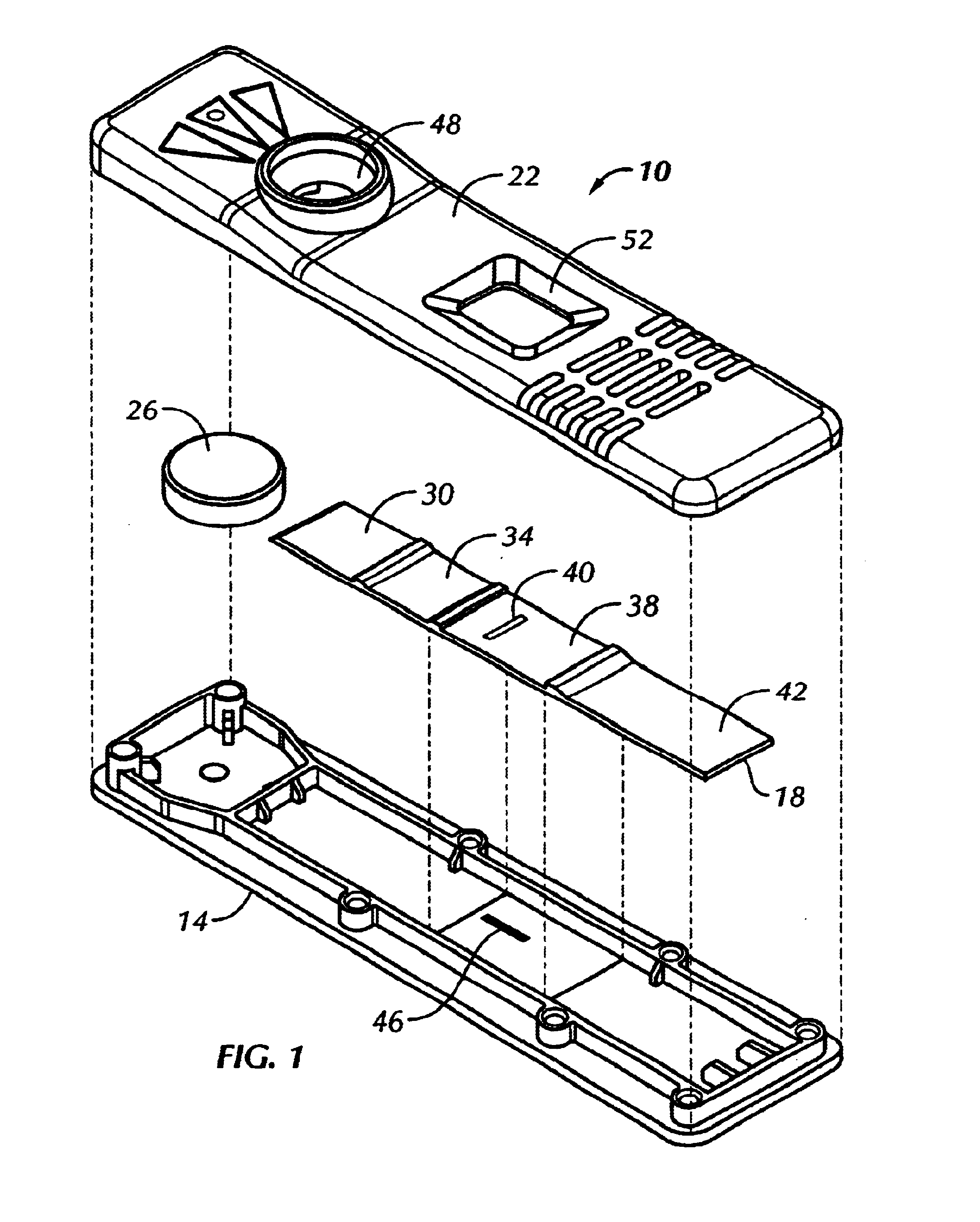
A lateral flow test device was constructed according to principles of the present invention. The test device included a G-III plastic bottom (#Z0846500), a G-III plastic scanner top (#Z0440900), a sample pad containing stock assay reagent, a label pad containing stock assay reagent, an observation zone as described below, and an absorbent pad (#0841000).
A nitrocellulose web assembly membrane from Millipore, trade name Highflow Plus Membrane, was combined with a clear Mylar backing.
A dark line was made on the inside of the plastic bottom, positioned parallel to sample flow in approximately the same area as would be underneath the fixed minus line from a current assay strip.
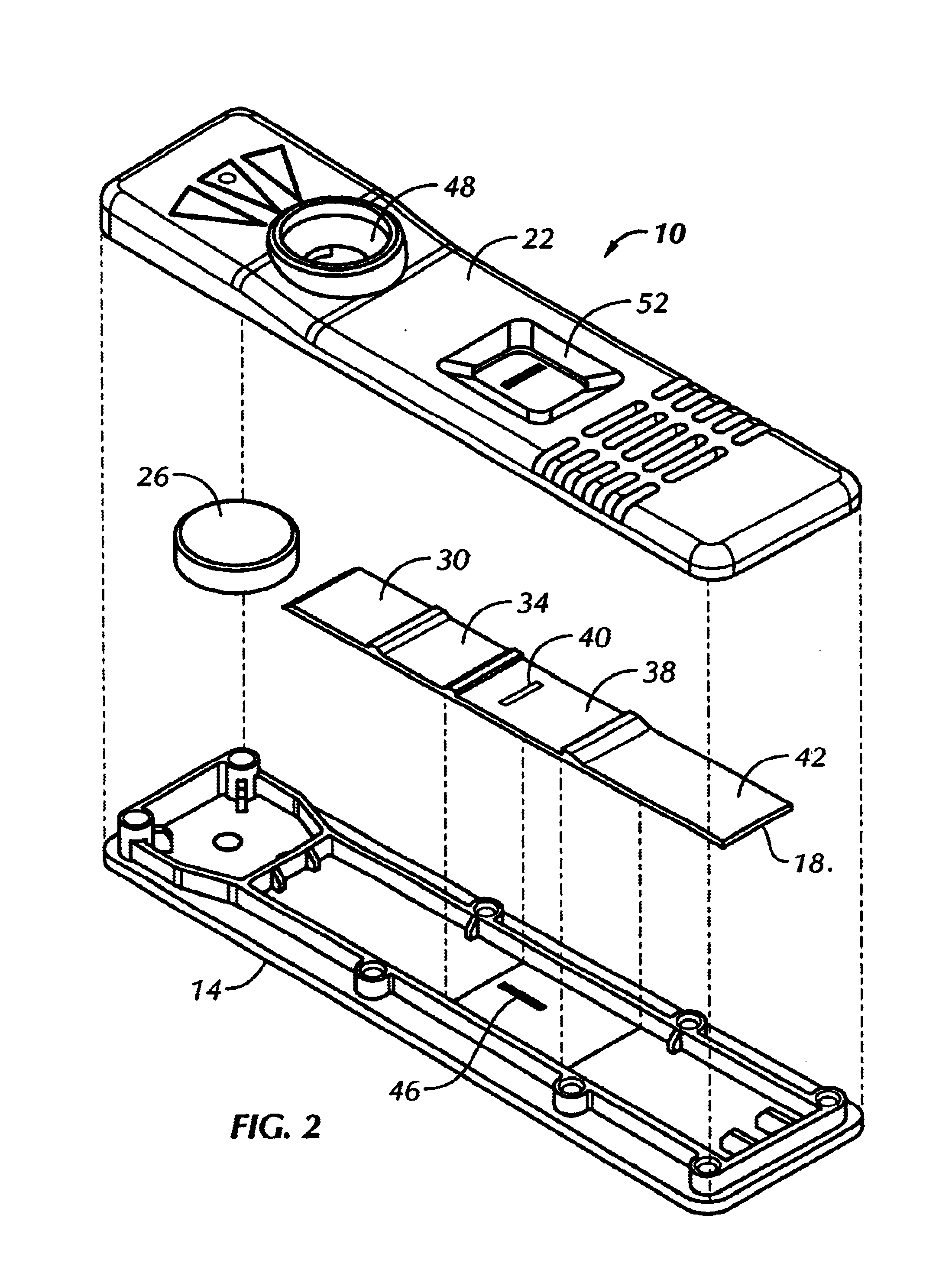
This bottom was then assembled with an experimental G-IV assay strip as described above, and a plastic scanner top. When a liquid sample was added to the test unit, the dark line, which was barely visible through the dry strip, became clearly visible. The results are shown generally in FIG. 2.
example 2
Goat anti-alpha hCG antibodies were immobilized on Hi-flow plus nitrocellulose membrane (nitrocellulose membrane cast on a transparent nylon sheet), manufactured by Millipore Inc. A second, unrelated protein was immobilized on the membrane for the procedural control line. The membrane was then blocked with a protein solution and dried prior to assembly.
A sample pad (non-woven rayon fiber backed with mylar) was impregnated with a buffered protein solutions and dried.
The label pad (non-woven rayon fiber backed with mylar) was impregnated with a solution containing red colored polystyrene microspheres coated with anti-beta hCG monoclonal antibodies, blue colored polystyrene microspheres coated with a binding pair member to the control line protein, and stabilizing agents followed by a drying process.
The sample and label pad, the capture membrane and an absorbent pad were then assembled into a test strip similar to FIG. 4.
A visible line was printed onto the bottom half of the plastic ho...
PUM
Abstract
A test device and method for determining the presence or absence of an analyte in a fluid sample, the test device including a support bearing a mark thereon, and a matrix defining an axial flow path. In operation, an observation area in the test device becomes transparent, thereby allowing the user to view a mark that is present on a support that is disposed beneath the observation area. Typically, the mark on the underlying support is configured as a minus (−) sign. In the absence of analyte in the sample, the test device presents a negative result as a minus (−) signal. In the presence of analyte in the sample, however, the mark operates in concert with a perpendicular test line on the observation area to present a positive result as a plus (+) signal that is visible to the user.
Description
CROSS-REFERENCES TO RELATED APPLICATIONSNot ApplicableSTATEMENT AS TO RIGHTS TO INVENTIONS MADE UNDER FEDERALLY SPONSORED RESEARCH OR DEVELOPMENTNot ApplicableREFERENCE TO A “SEQUENCE LISTING,” A TABLE, OR A COMPUTER PROGRAM LISTING APPENDIX SUBMITTED ON A COMPACT DISKNot ApplicableBACKGROUND OF THE INVENTIONThe present invention relates generally to devices and methods for detection of analytes in test samples. More specifically, the present invention provides solid phase test strip devices and methods that combine an internal indicator on the test strip with an external mark located on a support.Various analytical procedures and devices are commonly employed in detection assays to determine the presence and / or amount of substance of interest or clinical significance which may be present in biological or non-biological fluids. Such substances are generally termed “analytes” and can include antibodies, antigens, drugs, or hormones.The present invention includes lateral flow chromato...
Claims
Application Information
Patent Timeline
Application Date:The date an application was filed.
Publication Date:The date a patent or application was officially published.
First Publication Date:The earliest publication date of a patent with the same application number.
Issue Date:Publication date of the patent grant document.
PCT Entry Date:The Entry date of PCT National Phase.
Estimated Expiry Date:The statutory expiry date of a patent right according to the Patent Law, and it is the longest term of protection that the patent right can achieve without the termination of the patent right due to other reasons(Term extension factor has been taken into account ).
Invalid Date:Actual expiry date is based on effective date or publication date of legal transaction data of invalid patent.

