Multi-band PIF antenna with meander structure

a technology of meander structure and antenna, applied in the direction of antenna earthing, radiating element structural form, resonance antenna, etc., can solve problems such as redesign of respective antennas, and achieve the effect of increasing the useable bandwidth of a pifa

Inactive Publication Date: 2005-02-15
SIEMENS INFORMATION & COMM NEWTWORKS INC +1
View PDF12 Cites 55 Cited by
  • Summary
  • Abstract
  • Description
  • Claims
  • Application Information

AI Technical Summary

Benefits of technology

The present invention overcomes the above-identified problems as well as other shortcomings and deficiencies of existing technologies by providing an apparatus and a system for increasing the useable bandwidth of a PIFA.

Problems solved by technology

A significant problem in designing a practical PIFA application is the trade off between obtaining a desired operating bandwidth and reducing the PIFA volume (area×thickness).
Thus, redesigning a product for a different frequency can cause problems in the redesign of the respective antenna.

Method used


Image

  • Multi-band PIF antenna with meander structure
  • Multi-band PIF antenna with meander structure
  • Multi-band PIF antenna with meander structure

Examples


Embodiment Construction

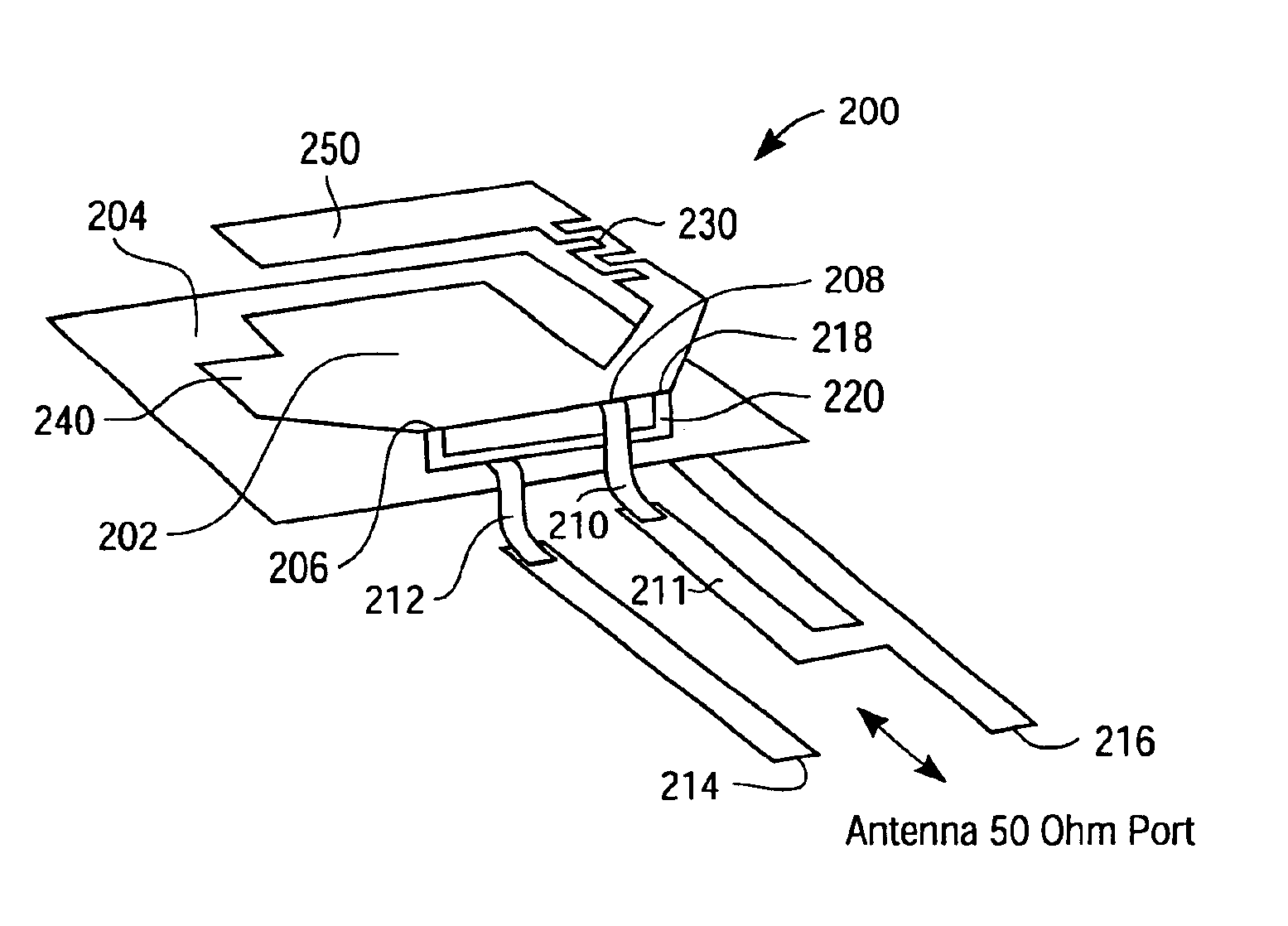
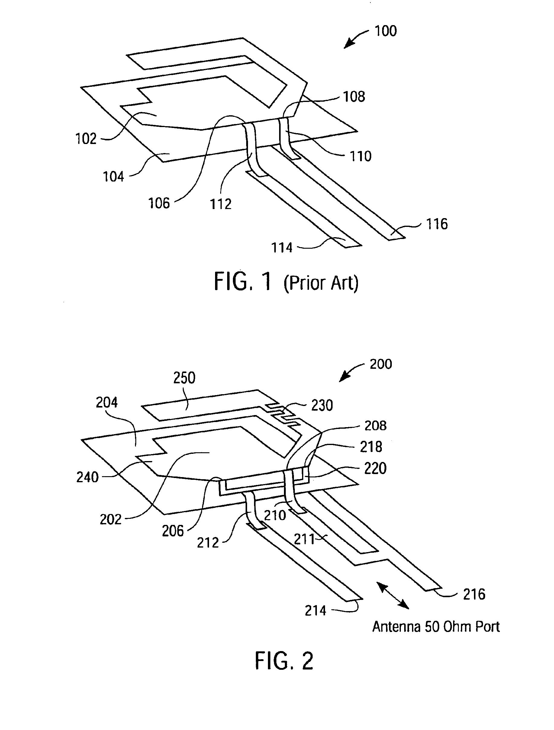
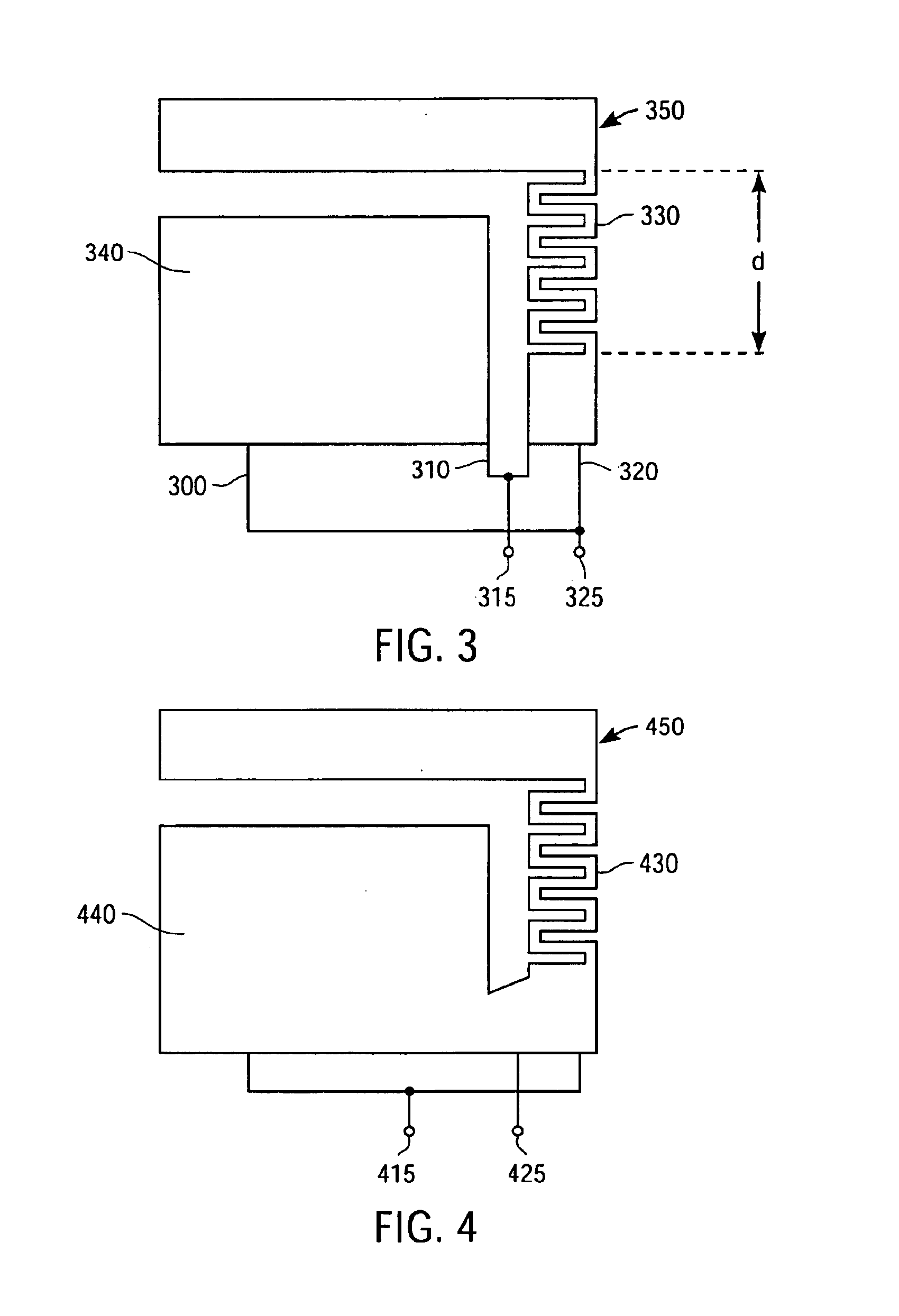
According to an exemplary embodiment of the invention, an antenna includes a ground plane and a radiating element. The ground plane has a first planar surface and a first area, and the radiating element has a second planar surface and a second area. The second planar surface of the radiating element is substantially parallel with the first planar surface of the ground plane, and the second area comprises a section having a meandering form elongating the effective over all length of the radiating element. The antenna may further comprise a first connecting line and a second connecting line. The first connecting line is coupled to a first edge of the ground plane and to a second edge of the radiating element at a first contact location, and the second connecting line is coupled to the second edge of the radiating element at second and third contact locations. The first area of the ground plane can be greater than the second area of the radiating element or can be substantially the sam...


PUM


Abstract

A mono-band or multi-band planar inverted F antenna (PIFA) structure comprises a planar radiating element having a first area, and a ground plane having a second area that is substantially parallel to the radiating element first area. The second area further comprises a section having a meandering form elongating the effective overall length of the radiating element.

Description

BACKGROUND OF THE INVENTIONThe present invention relates generally to antennas and more particularly to a multi-band planar inverted F antenna.Planar inverted F antennas (PIFAs) are used in wireless communications, e.g., cellular telephones, wireless personal digital assistants (PDAs), wireless local area networks (LANs)—Bluetooth, etc. The PIFA generally includes a planar radiating element having a first area, and a ground plane having a second area that is parallel to the radiating element first area. An electrically conductive first line is coupled to the radiating element at a first contact located at an edge on a side of the radiating element. The first line is also coupled to the ground plane. An electrically conductive second line is coupled to the radiating element along the same side as the first line, but at a different contact location on the edge than the first line. The first and second lines are adapted to couple to a desired impedance, e.g., 50 ohms, at frequencies of...

Claims


Application Information

Patent Timeline
Patent Type & Authority Patents(United States)
IPC IPC(8): H01Q9/04H01Q5/00H01Q1/24H01Q5/50
CPCH01Q1/243H01Q5/50H01Q9/0421H01Q1/38H01Q13/08
Inventor BETTIN, ULRICHNEVERMANN, PETER
Owner SIEMENS INFORMATION & COMM NEWTWORKS INC
Why Eureka
Try Eureka