Communication system, relay apparatus, end system, and communicating method

Inactive Publication Date: 2005-02-15
FUJITSU LTD
View PDF6 Cites 11 Cited by
  • Summary
  • Abstract
  • Description
  • Claims
  • Application Information

AI Technical Summary

Benefits of technology

According to the invention, there are provided a communication system, a relay apparatus, an end system, and a communicating method, in which with respect to a network that needs to establish a connection via a multi-stage relay apparatus to a partner destination end system, even if communication data is transmitted during a period of time until path information is updated by a routing protocol and an error is caused due to a path fault, a period of time that is required until a new path is selected and communication is started is shorten.

Problems solved by technology

Therefore, even if the establishment of the connection fails due to the path fault, the failure is not notified to the application, the connection via another relay apparatus is immediately established from the communicating source end system, and it is unnecessary to retransmit the communicating request from the application.
Therefore, even when a large-scale multiplexed network such as Internet, provider, or the like is switched, it is unnecessary to monitor a fault to the end system.
Consequently, such troublesomeness that the negative response is returned to the end system of the communicating source and another relay destination is selected is swept away and, further, the communication can be started in a short time.

Method used


Image

  • Communication system, relay apparatus, end system, and communicating method
  • Communication system, relay apparatus, end system, and communicating method
  • Communication system, relay apparatus, end system, and communicating method

Examples


first embodiment

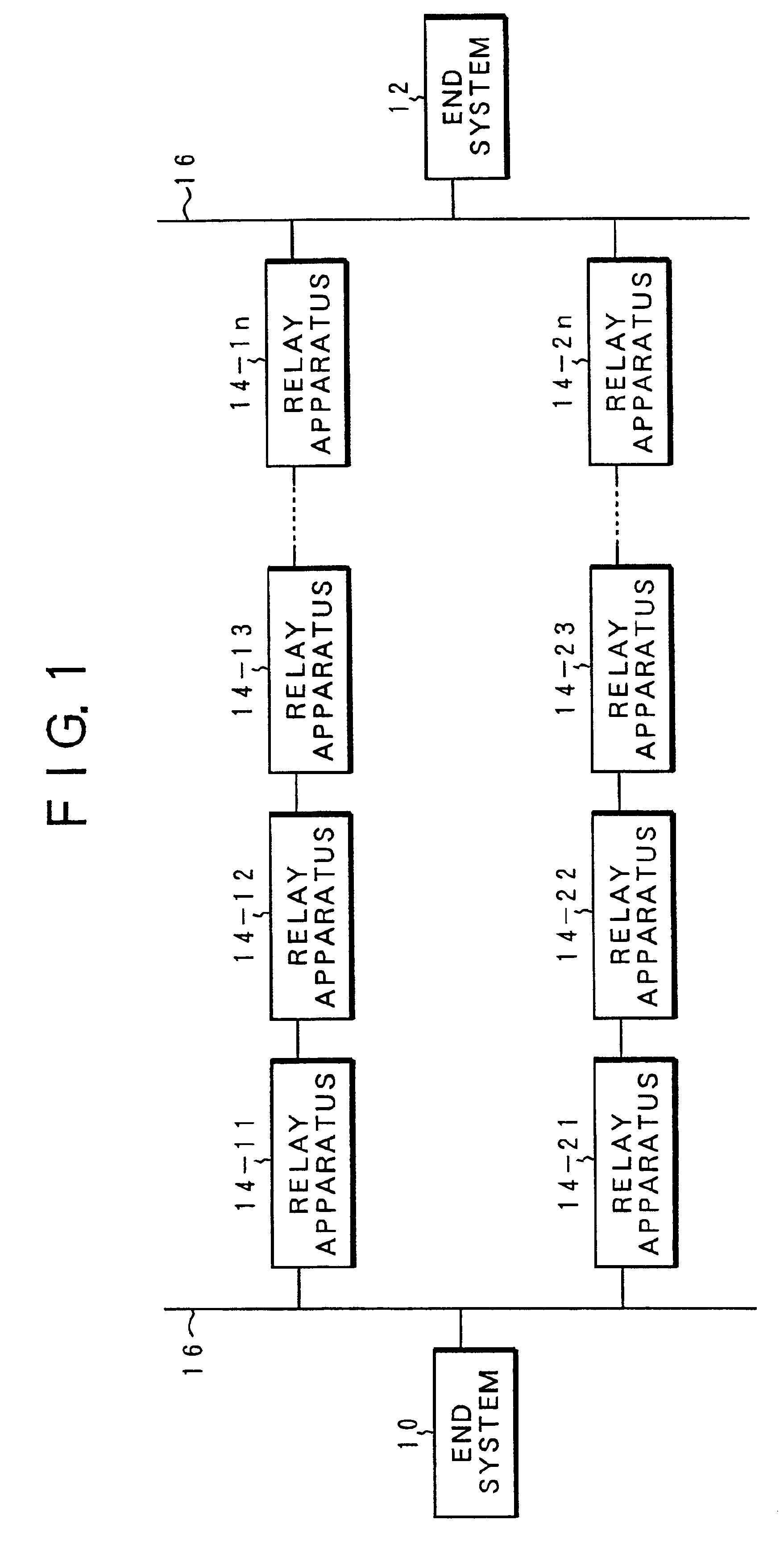
FIG. 1 shows a communication system according to the invention and is characterized in that a connection establishment request is switched on the end system side at the time of occurrence of a path fault. A network which constructs the communication system of the invention has an end system (self system) 10 serving as a communicating source and an end system (partner destination system) 12 serving as a communicating destination. A large-scale network which is multi-stage constructed by a plurality of relay apparatuses 14-11 to 14-1n and 14-21 to 14-2n and transmission paths 16 is constructed between the end systems 10 and 12. For example, there is the Internet, Ethernet, or the like as such a network.

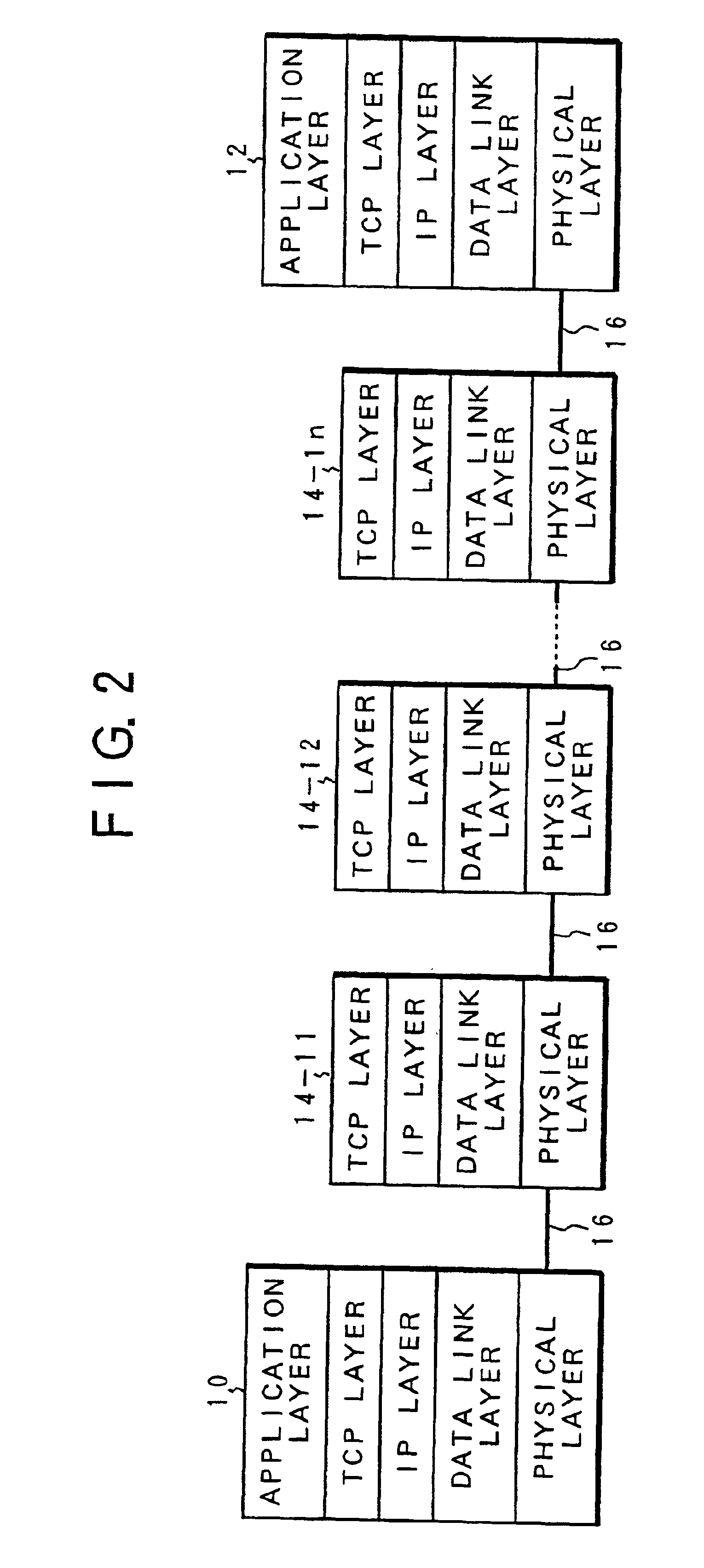
FIG. 2 shows a layer structure of the end systems 10 and 12 and the relay apparatuses with respect to the side of the relay apparatuses 14-11 to 14-1n. This network corresponds to a TCP / IP protocol. Each of the end systems 10 and 12 and the relay apparatuses 14-11 to 14-1n has a physica...

second embodiment

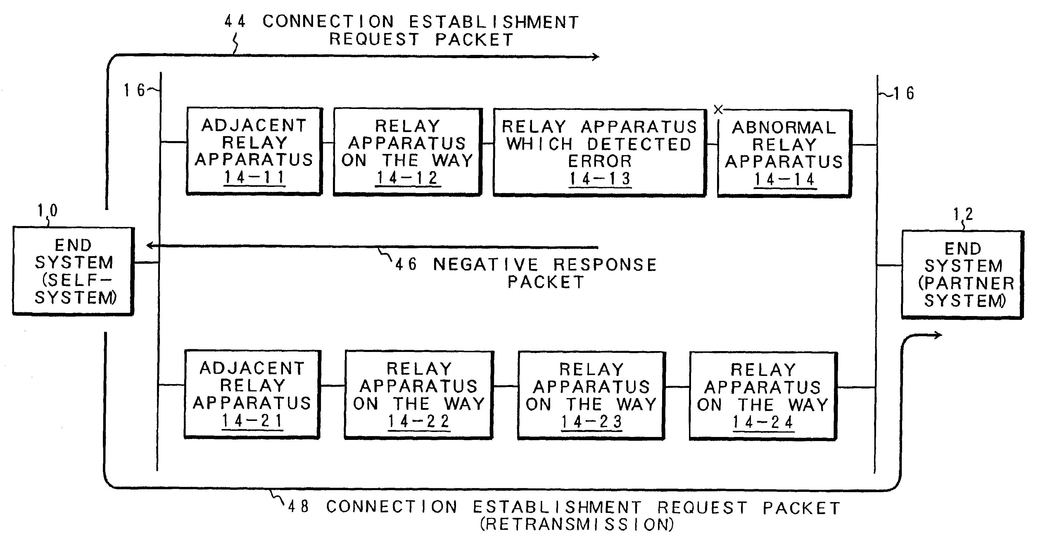
FIG. 14 is an explanatory diagram of a communicating process in the case where an error occurs in the relay apparatus at the halfway in FIG. 13. On the basis of the communicating request of the application of the end system 10, the end system 10 transmits a connection establishment request packet 53 to the adjacent relay apparatus 14-11. The connection establishment request packet 53 is relayed to the relay apparatuses 14-12 and 14-13. However, when it is relayed to the relay apparatus 14-13, the relay apparatus 14-13 recognizes an error of the next relay apparatus 14-14 and transmits a negative response packet 54 to the relay apparatus 14-12. The packet 54 is further transmitted from the relay apparatus 14-12 to the relay apparatus 14-11. The relay apparatus 14-11 which received the negative response packet 54 has the relay apparatus 14-22 as an alternative relay apparatus besides the relay apparatus 14-12 as a path fault relay destination. Therefore, after the status of the relay ...


PUM


Abstract

In a relay apparatus, when an error of the next relay destination is detected at the time of reception of a connection establishment request, the connection establishment request is refused by a connection negative response unit and a negative response relay unit, and a negative response is transmitted to a relay source. When the negative response is received from the relay destination, a connection establishment requesting unit of an end system of a communicating source again issues a connection establishment request in which another relay destination has been selected without notifying an application of a failure of the connection establishment, and establishes a connection to a communicating destination end system by another path.

Description

BACKGROUND OF THE INVENTION1. Field of the InventionThe present invention relates to a communication system, a relay apparatus, an end system, and a communicating method, in which a connection via a plurality of relay apparatuses is established between end systems for communicating and data is communicated. More particularly, the invention relates to a communication system, a relay apparatus, an end system, and a communicating method, in which upon occurrence of a path fault, it is tried to establish a connection by another path without notifying an application on a communicating source side of a communication error.2. Description of the Related ArtsHitherto, in a generally used routing protocol as well as the Internet by which a connection via a plurality of multiplexed relay apparatuses is established and data communication is performed between end systems, the respective relay apparatuses exchange routing information in addition to communication data, thereby selecting the optimu...

Claims


Application Information

Patent Timeline
Patent Type & Authority Patents(United States)
IPC IPC(8): H04L12/56H04L29/08H04L12/46H04L12/70
CPCH04L45/02H04L43/0811H04L45/28
Inventor NAKAJIMA, MASAKI
Owner FUJITSU LTD
Why Eureka
Try Eureka