
Power blower having a debris-catching filter member

a technology of filter member and blower, which is applied in the direction of filtration separation, turf growing, separation processes, etc., can solve the problems of affecting the air intake efficiency of the blower, and affecting the removal effect of prime mover, so as to achieve convenient removal

Inactive Publication Date: 2005-02-22
KIORITZ
View PDF9 Cites 18 Cited by
  • Summary
  • Abstract
  • Description
  • Claims
  • Application Information

AI Technical Summary

Benefits of technology

Accordingly, an object of the present invention is to provide a power blower that inhibits debris from collecting on the power blower and enables the convenient removal of debris that does happen to collect.
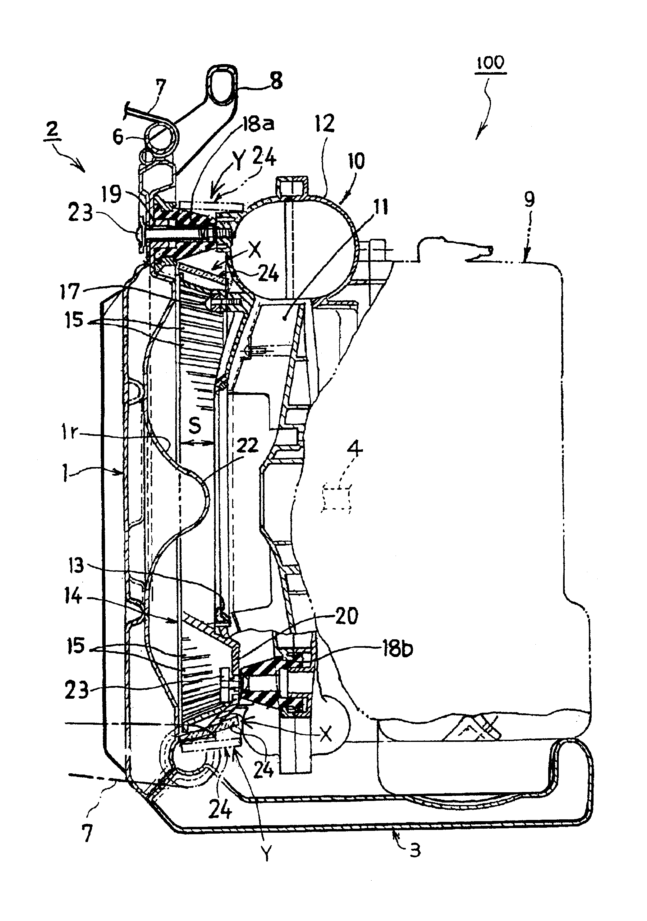
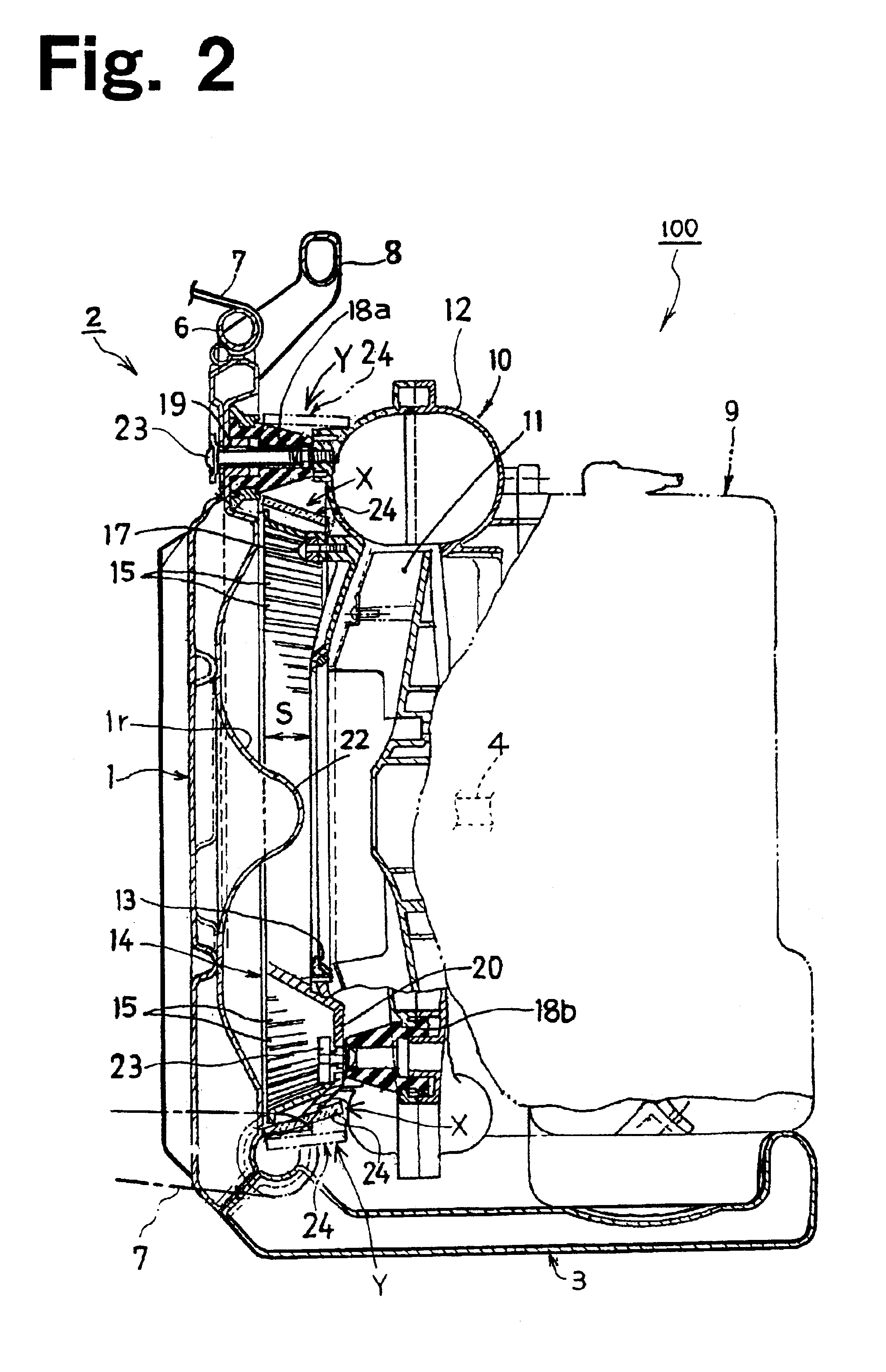
In another embodiment of the present invention, the filter member is formed of a brush member having debris-catching bristles planted in a flexible core member in a radial direction, and having an outer diameter corresponding to the width of the air intake space. In this case, the gaps between the bristles serve as breathing holes. In a further embodiment, the brush member has at least two engaging portions adapted to engage and disengage each other. For example, each end of the brush member could have an engaging portion (e.g., a hook on one end and a ring on the other end) to connect and disconnect the ends of the member together, for attaching the filter member to and detaching the filter member from the power blower. In this manner, a user can conveniently and quickly remove debris caught by the filter member.

Problems solved by technology

Unfortunately, when the air intake port is covered by the ventilation cover, debris such as fallen leaves may stick to the ventilation cover due to the incoming airflow.
This obstruction can disadvantageously lower the air intake efficiency of the blower, and can damage the prime mover (e.g., gasoline engine) driving the blower by impeding the supply of cooling air.
However, removal of debris is a complicated and time-consuming effort because the user must insert his or her hand deep within the typically narrow air intake space.
Therefore, the efficiency of both the user and the power blower is compromised.

Method used


Image

  • Power blower having a debris-catching filter member
  • Power blower having a debris-catching filter member
  • Power blower having a debris-catching filter member

Examples


Embodiment Construction

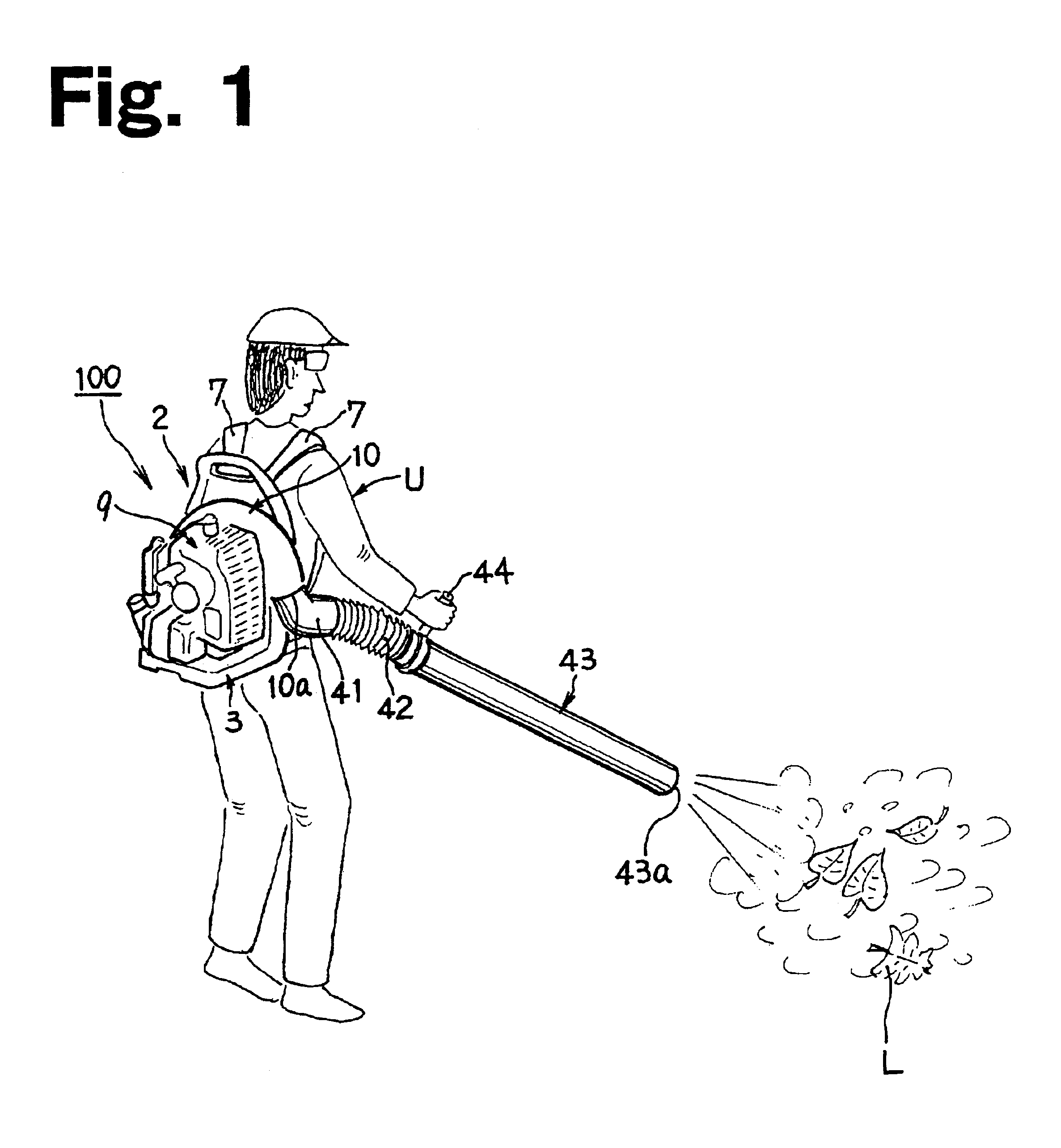
FIG. 1 illustrates a power blower 100 according to an embodiment of the present invention. As shown, the power blower 100, which in this example is a backpack-type power blower, includes a backpack frame 2. In this specific implementation, the backpack frame 2 has a pair of left and right shoulder belts 7 for carrying the frame 2 on the back of a user U. A blower 10, such as a centrifugal-type blower, is mounted on the frame 2. An internal combustion engine 9, such as an air-cooled two-cycle gasoline engine, is also mounted on the frame 2 and acts as a prime mover for driving the blower 10. An air-blowing pipe 43 is connected via an elbow pipe 41 and a bellows hose 42 to an air discharging port 10a of the blower 10.

The user U puts the backpack frame 2 on his or her back with the pair of left and right shoulder belts 7, holds a handle 44 attached to the proximal end of the air-blowing pipe 43, and drifts debris, such as fallen leaves L, by blowing air from the discharging port 43a of...


PUM

PropertyMeasurementUnit
Diameteraaaaaaaaaa
Flexibilityaaaaaaaaaa
Widthaaaaaaaaaa

Abstract

A power blower having a frame, a blower, and a loop-shaped filter member. In an embodiment of the invention, the blower is disposed apart from the frame by an air intake space and has an air intake port facing the frame, and the loop-shaped filter member is disposed around a periphery of the air intake port and is adapted to catch debris on an upstream side of the air intake port.

Description

This application claims the benefit of Japanese Patent Application Number 2001-155247, filed May 24, 2001.BACKGROUND1. Field of the InventionThe present invention relates to power blowers, and more specifically, to a power blower that inhibits debris from collecting around the air intake space of the blower and provides convenient means for removing debris that does collect.2. Background of the InventionBackpack-type power blowers (also commonly referred to as leaf blowers and yard blowers) are typically used to drift fallen leaves and lawn clippings. The motor-driven fan of a power blower draws air in through an air intake port and forces air out through a discharge port. The air intake port is typically covered with a meshed ventilation cover to prevent objects from entering the air intake port and contacting the fan.Unfortunately, when the air intake port is covered by the ventilation cover, debris such as fallen leaves may stick to the ventilation cover due to the incoming airfl...

Claims


Application Information

Patent Timeline
IPC IPC(8): A47L9/10A47L5/14A47L5/12B01D41/00A01G1/12B01D41/04E01H1/08
CPCA01G1/125B01D41/04A47L9/127A47L5/14A01G20/47
Inventor IIDA, GIICHIKAMOSHITA, TADASHI
Owner KIORITZ
Learn More