Construction element and coupling device therefor

a technology of construction elements and coupling devices, which is applied in the direction of couplings, rod connections, manufacturing tools, etc., can solve the problems of complex fabrication of such elements

Inactive Publication Date: 2005-02-22
ADAMS MFG
View PDF10 Cites 22 Cited by
  • Summary
  • Abstract
  • Description
  • Claims
  • Application Information

AI Technical Summary

Benefits of technology

In yet another embodiment of the subject invention, a construction element system is comprised of a plurality of interconnected construction elements secured to one another by coupling devices, wherein each construction element has a core and wherein each coupling device is comprised of a base with a coupling axis and at least two spaced-apart prongs which extend from the base and are parallel to the coupling axis, wherein each prong is comprised of: (a) two radially extending mating surfaces, each having a first and second end; (b) an inner transition surface connecting the first ends of each mating surface; (c) an outer transition surface connecting the second ends of each mating surface; and (d) wherein each mating surface forms an equal but opposite angle with a common baseline connecting the second end of each mating surface.

Problems solved by technology

While this positive-lock feature may be desirable in certain circumstances, fabrication of such an element is complex.

Method used


Image

  • Construction element and coupling device therefor
  • Construction element and coupling device therefor
  • Construction element and coupling device therefor

Examples


Embodiment Construction

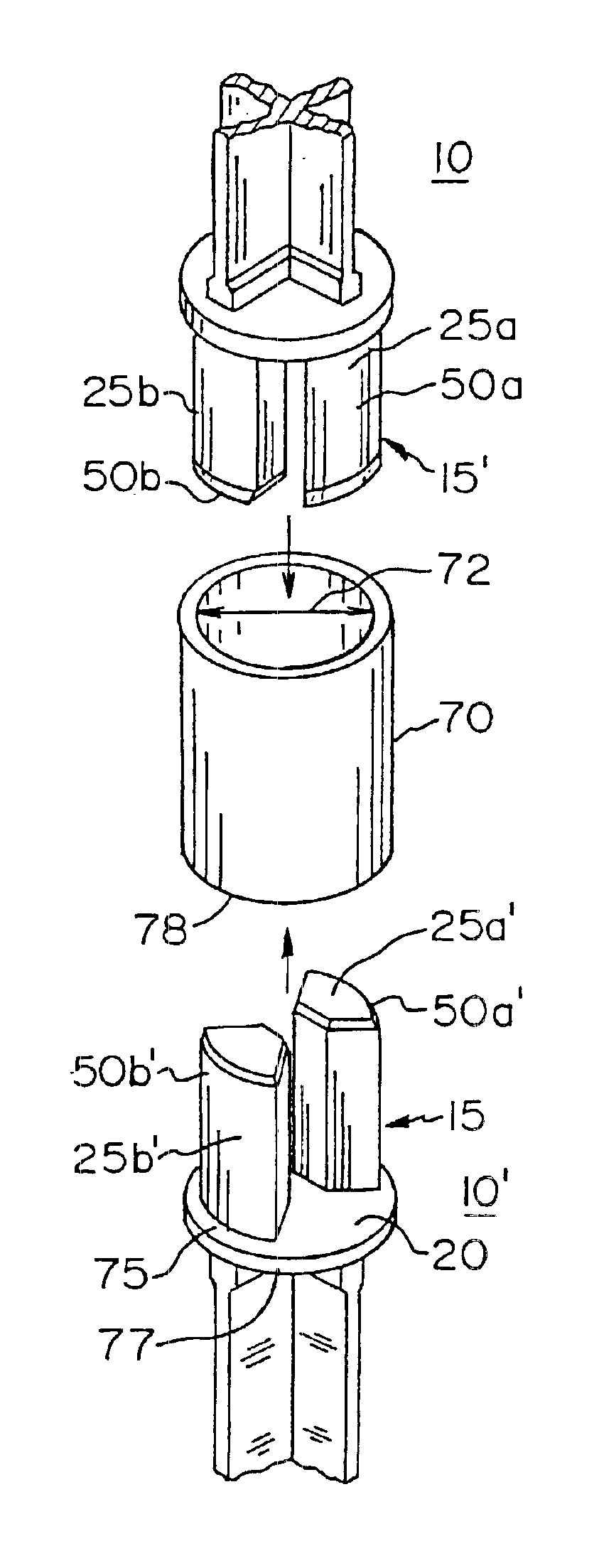
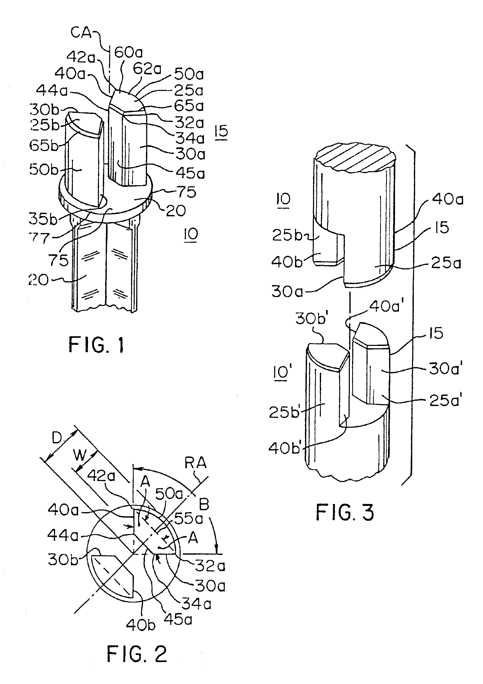
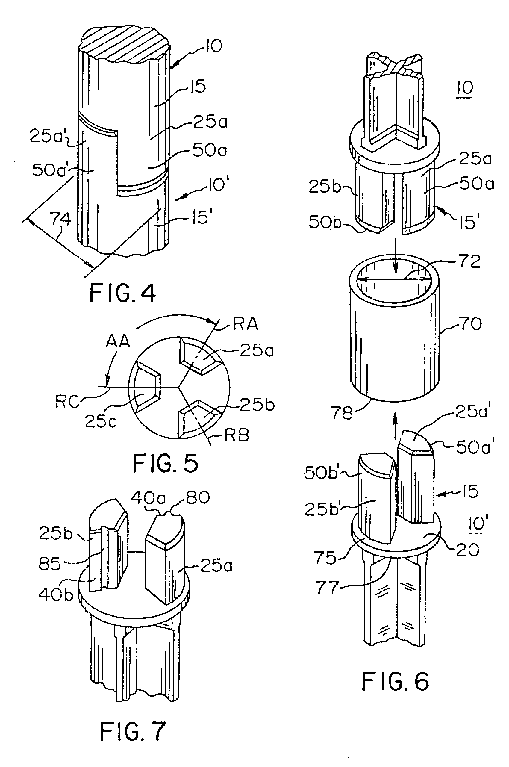
FIG. 1 illustrates a portion of a construction element 10 having a coupling device 15. FIG. 2 illustrates a top view of the coupling device 15. The couple device is comprised of a base 20 with a coupling axis CA and at least two spaced-apart prongs 25a, 25b which extend from the base 20 and are parallel to the coupling axis CA.

Prongs 25a, 25b are identical to one another with the exception that they are located about the coupling axis CA at radially opposing positions. For that reason and with this exception, the discussion will be directed to prong 25a with the understanding that each feature discussed in 25a is also present in 25b.

Prong 25a has two radially extending mating surfaces 30a and 40a. Mating surface 30a has a first end 32a and a second end 34a, while mating surface 40a has a first end 42a and a second end 44a. An inner transition surface 45a connects the second ends 34a, 44a of each mating surface 30a, 40a. An outer transition surface 50a connects the first ends 32a, 4...


PUM


Abstract

A construction element has at least one coupling device and the coupling device has at least two prongs. Each prong is comprised of two radially extending mating surfaces which frictionally engage the radially extending surfaces of a mating coupling device. The construction device may have a straight shaft or an angled shaft to accommodate the needs of the user and, furthermore, the prongs of a coupling device may be inserted within mateable apertures in the shaft of another construction element. Using a plurality of such construction elements, a lattice frame may be constructed.

Description

BACKGROUND OF THE INVENTION1. Field of the InventionThe present invention relates to construction elements and, more particularly, to a construction element with a coupling device for use in a lattice structure.2. Description of the Related ArtConstruction elements may be comprised of connector elements and structural elements. These elements may be combined in various configurations to form composite structures.U.S. Pat. No. 5,704,186 describes a construction element having opposing jaws which expand and lock upon protrusions extending from an adjacent construction element. While this positive-lock feature may be desirable in certain circumstances, fabrication of such an element is complex.It is an object of the present invention to provide a construction element intended for a lattice structure in which the construction element utilizes a coupling device that is relatively simple and provides a secure attachment when mated with another coupling device.Other objects of the present ...

Claims


Application Information

Patent Timeline
Patent Type & Authority Patents(United States)
IPC IPC(8): E04B1/58F16B7/04F16B7/08
CPCE04B1/58E04B1/5843F16B7/0426Y10T403/341Y10T403/344Y10T403/7026Y10T403/3906Y10T403/7045Y10T403/559Y10T403/7016F16B7/00
Inventor ADAMS, WILLIAM E.
Owner ADAMS MFG
Why Eureka
Try Eureka