
Conical tip shroud fillet for a turbine bucket

a turbine bucket and conical tip technology, applied in the field of variable conical fillets, can solve the problems of premature failure of the bucket, reduced creep life of the tip shroud, and significant decreases in the life of the bucket, so as to minimize stress, minimize creep as well as the mass of the fillet, and reduce the effect of reducing the stress

Inactive Publication Date: 2005-02-22
GENERAL ELECTRIC CO
View PDF6 Cites 50 Cited by
  • Summary
  • Abstract
  • Description
  • Claims
  • Application Information

AI Technical Summary

Benefits of technology

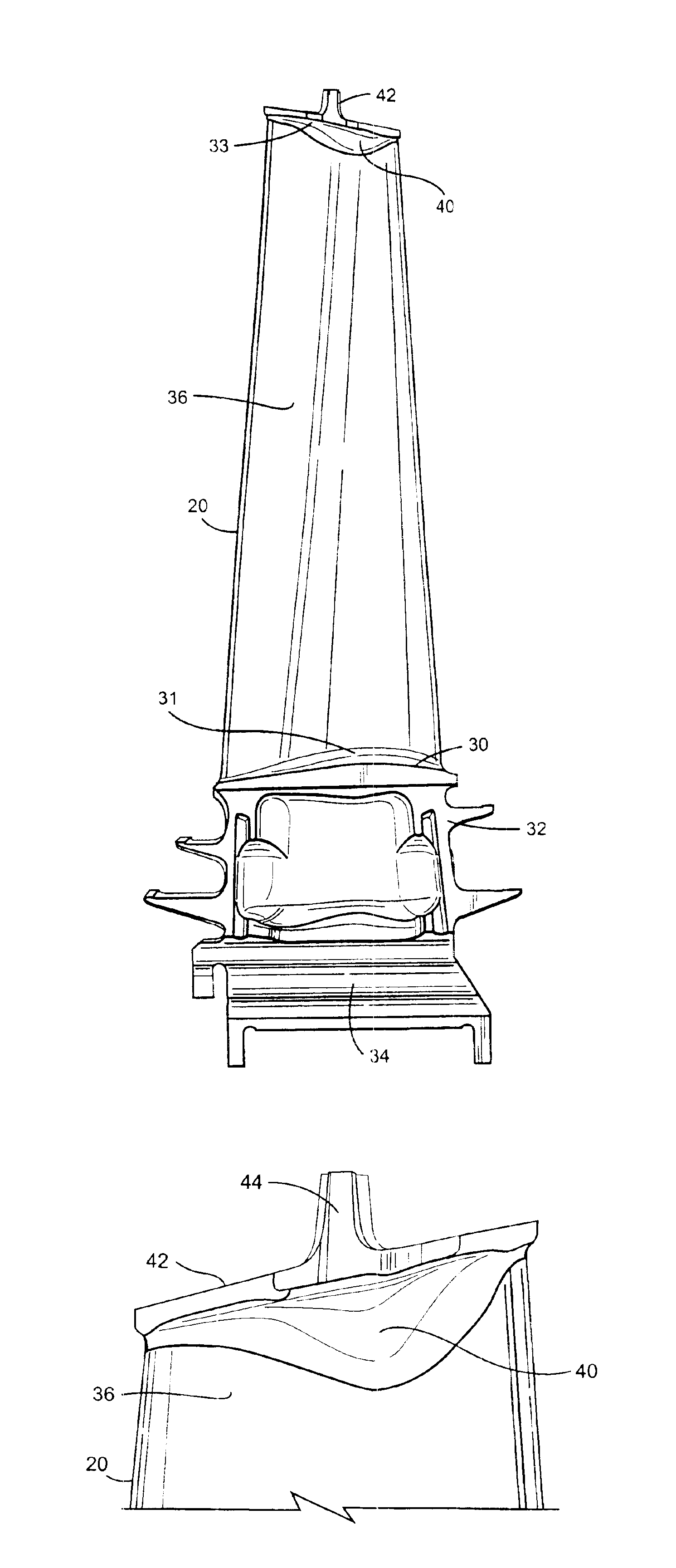
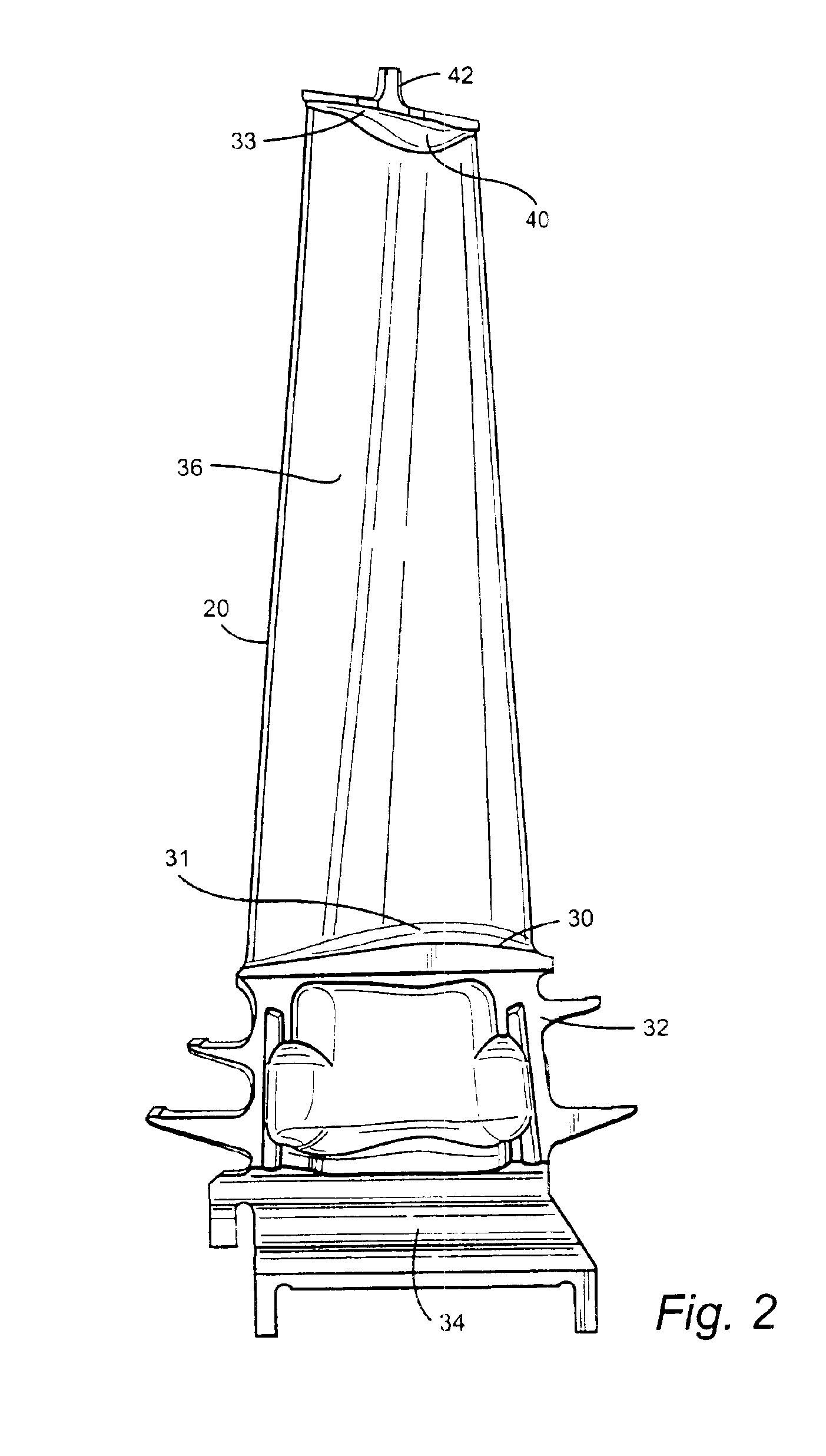
In accordance with the preferred embodiment of the present invention, there is provided a variable conical fillet between the airfoil tip and the tip shroud which minimizes creep as well as the mass of the fillet by varying the fillet size and configuration as a function of the high localized stresses about the intersection of the airfoil tip and tip shroud. The variable conical fillet profile is a function of an offset 1, an offset 2, Rho and discrete X, Y apex locations about the intersection of the airfoil and tip shroud. Offset 1 is a distance normal to the airfoil surface at each apex location projected along the airfoil surface and offset 2 is a distance extending normal to the tip shroud undersurface at each apex location projected along the tip shroud undersurface. Normals projected onto the airfoil surface and tip shroud undersurface from the intersection of offsets 1 and 2 define edge points which, upon connection about the respective tip shroud and airfoil, form the edges of the fillet. The offsets are determined by finite element stress analysis to minimize stress. Rho is a shape parameter defining the shape of the fillet at each apex location. These factors are utilized at various X and Y locations about the intersection of the airfoil tip and tip shroud, enabling the fillet to take on a variably configured profile at each location to evenly distribute the stress about the fillet while simultaneously minimizing the mass added to the bucket fillet. The shape of the fillet is thus biased toward the tip shroud or to the airfoil as determined by the stress analysis at the particular location under consideration whereby the high local stresses are accommodated and the mass of the fillet is minimized.
Particularly, the optimized conical tip shroud fillet hereof is defined, in a preferred embodiment, by 15 locations or points about the intersection of the tip shroud and airfoil tip with each location having three parameters, i.e., offset 1, offset 2 and Rho, which define the extent and shape of the fillet at that location. By varying the fillet in accordance with these parameters about the intersection, tip shroud creep life can be maximized while minimizing the mass of the bucket at the fillet. Particular locations and parameters are set forth in Table I below for the tip shroud / airfoil fillet of a second stage of a three stage turbine having 92 buckets. It will be appreciated that the number of locations at which these parameters are applied may vary while maintaining the shape of the fillet within a robust envelope sufficient to achieve the objectives of maximizing creep life and reducing bucket mass.

Problems solved by technology

While the stresses were reduced by use of constant radius fillets, it was discovered that high stresses in the fillet region were localized at various locations or points in and about the fillet between the airfoil and tip shroud and that such localized stresses lead to significant decreases in bucket life.
These stresses reduced the creep life of the tip shroud which can lead to premature failure of the bucket.
This is a time-consuming and costly outage, causing the customer as well as the turbine producer to incur higher costs due to unproductivity, labor, part repair, outage time and replacement.

Method used


Image

  • Conical tip shroud fillet for a turbine bucket
  • Conical tip shroud fillet for a turbine bucket
  • Conical tip shroud fillet for a turbine bucket

Examples


Embodiment Construction

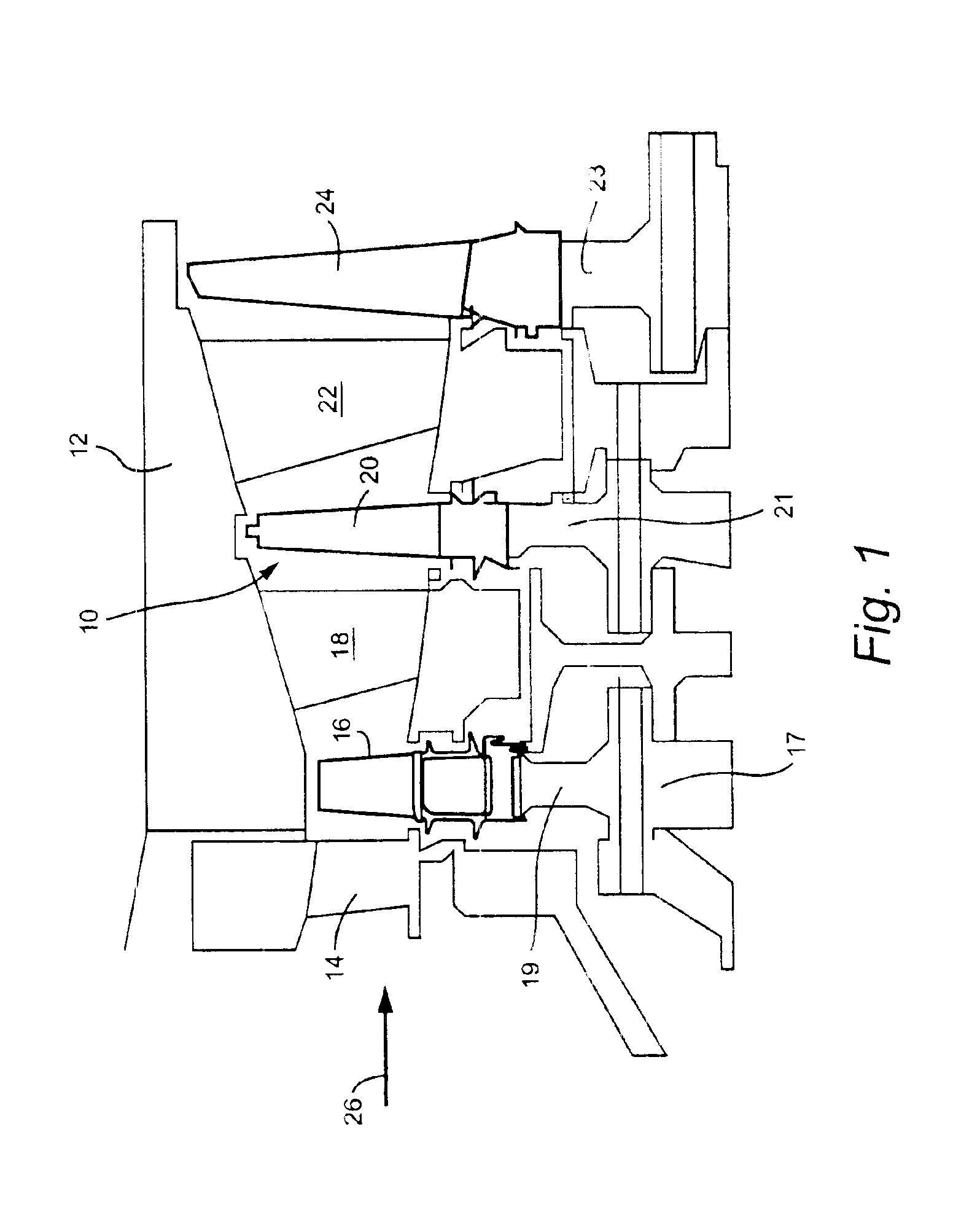
Referring now to the drawings, particularly to FIG. 1, there is illustrated a hot gas path, generally designated 10, of a gas turbine 12 including a plurality of turbine stages. Three stages are illustrated. For example, the first stage comprises a plurality of circumferentially spaced nozzles 14 and buckets 16. The nozzles are circumferentially spaced one from the other and fixed about the axis of the rotor. The first stage buckets 16, of course, are mounted on the turbine rotor 17 via a rotor wheel 19. A second stage of the turbine 12 is also illustrated, including a plurality of circumferentially spaced nozzles 18 and a plurality of circumferentially spaced buckets 20 mounted on the rotor 17 via a rotor wheel 21. The third stage is also illustrated including a plurality of circumferentially spaced nozzles 22 and buckets 24 mounted on rotor 17 via a rotor wheel 23. It will be appreciated that the nozzles and buckets lie in the hot gas path 10 of the turbine, the direction of flow ...


PUM


Abstract

A turbine bucket airfoil has a conical fillet about the intersection of the airfoil tip and tip shroud having a nominal profile in accordance with coordinate values of X and Y, offset 1, offset 2 and Rho set forth in Table I. The shape parameters of offset 1, offset 2 and Rho define the configuration of the fillet at the specified X and Y locations about the fillet to provide a fillet configuration accommodating high localized stresses. The fillet shape may be parabolic, elliptical or hyperbolic as a function of the value of the shape parameter ratio of D1D1+D2at each X, Y location where Dl is a distance between an intermediate point along a chord between edge points determined by offsets O2 and O2 and a shoulder point on the fillet surface and D2 is a distance between the shoulder point and an apex location at the intersection of the airfoil tip and tip shroud.

Description

BACKGROUND OF THE INVENTIONThe present invention relates to a variable conical fillet between an airfoil tip of a turbine bucket and a bucket tip shroud and particularly relates to a conical fillet shaped and sized to improve part life, performance and manufacturing of the turbine bucket.Turbine buckets generally comprise an airfoil, a platform, shank and dovetail along a radial inner end portion of the bucket and often a tip shroud at the tip of the airfoil in mechanical engagement with tip shrouds of adjacent buckets. The tip shroud and airfoil of a conventional turbine bucket are typically provided with a simple fillet shape of a predetermined size and generally of a constant radius about the intersection of the tip shroud and the airfoil tip. That is, a generally uniform radius was applied to the shroud fillet as the fillet was applied about the intersection of the airfoil tip and tip shroud. The fillet lowered the stress concentration between the airfoil and tip shroud.While th...

Claims


Application Information

Patent Timeline
Patent Type & Authority Patents(United States)
IPC IPC(8): F01D5/14F01D11/08F01D5/16
CPCF01D5/147F01D5/225F05D2260/94Y10S415/914F05D2250/70F05D2250/14F05D2250/17F05D2250/16Y02T50/60
Inventor TOMBERG, STEVEN ERICNEELEY, MARVIN LUTHER
Owner GENERAL ELECTRIC CO
Learn More