Switched-capacitor structures with enhanced isolation

a technology of capacitors and isolation, applied in the direction of instruments, lighting and heating apparatus, code conversion, etc., can solve the problems of less than desired isolation from input circuits, and achieve the effect of increasing upstream and downstream isolation

Active Publication Date: 2005-02-22
ANALOG DEVICES INC
View PDF11 Cites 48 Cited by
  • Summary
  • Abstract
  • Description
  • Claims
  • Application Information

AI Technical Summary

Benefits of technology

The present invention is directed to switched-capacitor structures that increase upstream and downstream isolation between structural elements.

Problems solved by technology

Although switched-capacitor structures are especially suited for accurate realization with integrated-circuit photolithographic techniques, their isolation from input circuits has generally been less than desired.

Method used


Image

  • Switched-capacitor structures with enhanced isolation
  • Switched-capacitor structures with enhanced isolation
  • Switched-capacitor structures with enhanced isolation

Examples


Embodiment Construction

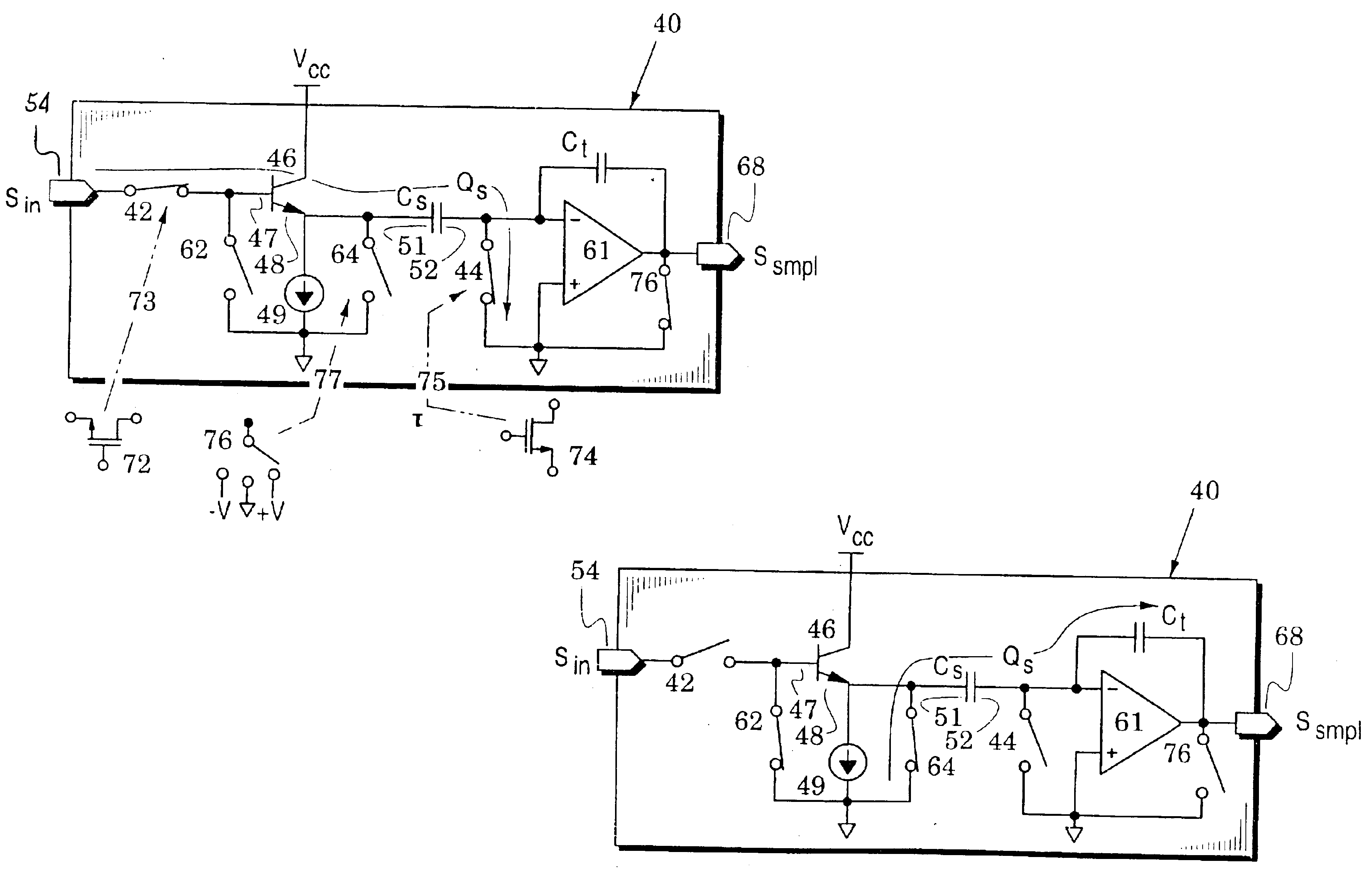
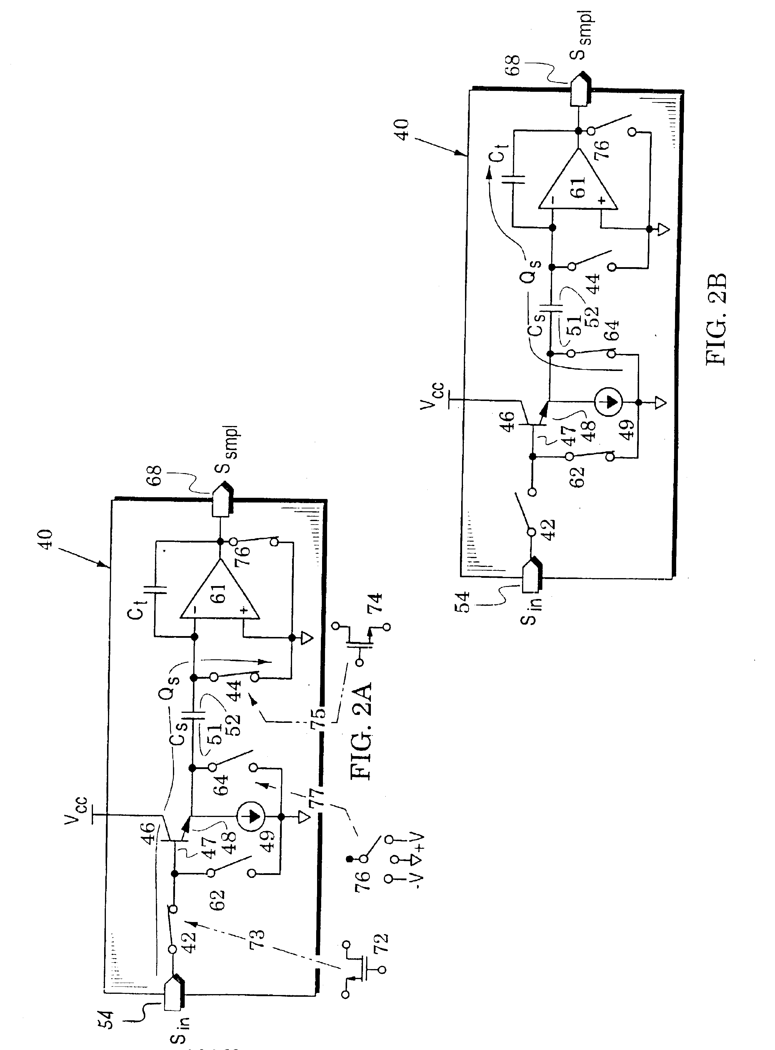
FIGS. 2A and 2B illustrate a switched-capacitor embodiment 40 which is suitable for sampling an analog input signal Sin in a sample mode of operation and providing a sample signal Ssmpl at an output port during a transfer mode of operation. When used as a sampler (e.g., as shown in FIG. 1D), the embodiment 40 effectively enhances and ensures upstream isolation.

In particular, the sampler 40 includes first and second sample switches 42 and 44 and a buffer transistor 46 which has a control terminal 47 coupled to the first sample switch 42 and has a current terminal 48 that is responsive to the control terminal 47. The current terminal is coupled to a current source 49 and another current terminal is coupled to a bias voltage (e.g., Vcc). A sample capacitor Cs has a bottom plate 51 coupled to the current terminal 48 and a top plate 52 coupled to the second sample switch 44. The first sample switch 42 is coupled to a sampler input port 54 to receive an analog input signal Sin.

In addition...


PUM

PropertyMeasurementUnit
currentaaaaaaaaaa
chargeaaaaaaaaaa
charge Qsaaaaaaaaaa

Abstract

Switched-capacitor structures are provided that reduce distortion and noise in their processed signals because they increase isolation between structural elements and ensure that selected elements are securely turned off in one mode and quickly turned on in another mode.

Description

BACKGROUND OF THE INVENTION1. Field of the InventionThe present invention relates generally to switched-capacitor structures.2. Description of the Related ArtFIGS. 1A and 1B illustrate a conventional switched-capacitor structure 10 in which a sample capacitor Cs. has a top plate 11 coupled to the inverting input of a differential amplifier 12 and a bottom plate 13 coupled through a first sample switch 14 to an input port 15. The differential amplifier 12 drives an output port 16 and a transfer capacitor Ct is coupled across the differential amplifier. The differential amplifier has a high gain so that its non-inverting input has substantially the same potential as its inverting input. Finally, a second sample switch 17 and a transfer switch 18 are respectively coupled to the top and bottom plates 11 and 13. The first and second sample switches 14 and 17 and the transfer switch 18 are generally realized with transistors.FIG. 1A illustrates a sample operation of the switched-capacitor...

Claims


Application Information

Patent Timeline
Patent Type & Authority Patents(United States)
IPC IPC(8): H03H19/00H03M1/08H03M1/14H03M1/38H03M1/44H03M1/16C08F236/10H03M1/12
CPCH03H19/004H03M1/08H03M1/442H03M1/168
Inventor MICHALSKI, CHRISTOPHER
Owner ANALOG DEVICES INC
Why Eureka
Try Eureka