Drive control method for photosensor system

a technology of photosensors and control methods, which is applied in the direction of color television, television systems, and scanning details of the system, can solve the problems of inability to start the read operation of the subject image promptly with an appropriate sensitivity, and the practicability of the photosensor array is very limited, so as to shorten the time required for the read operation

Inactive Publication Date: 2005-02-22
CASIO COMPUTER CO LTD
View PDF6 Cites 20 Cited by
  • Summary
  • Abstract
  • Description
  • Claims
  • Application Information

AI Technical Summary

Benefits of technology

An object of the present invention is to provide a drive control method that permits shortening the time required for the read operation of an image of a subject in a photosensor system including a plurality of photosensors arranged to form a two dimensional array.
Another object of the present invention is to provide a drive control method of a photosensor system that permits promptly executing the read operation of an image of a subject with a detecting sensitivity adapted for the state of use.
A first drive control method of the present invention for achieving the objects noted above is directed to a drive control method for shortening the time required for a read processing of an image of a subject. Specifically, while performing the reset operation in advance by successively applying reset pulses to each row, read pulses are successively applied to the row having a pre-charge pulse applied thereto to finish the pre-charge operation after the charge accumulating period so as to read the output voltage of the photosensor. What should be noted is that the processing cycles for the rows are allowed to overlap in time with each other so as to shorten the read processing time of a single screen. The particular drive control method is characterized in that the interval of the reset pulse, read pulse and pre-charge pulse for each row is set equal to the sum of the reset period performed by the reset pulse, the read period performed by the read pulse, and the pre-charge period performed by the pre-charge pulse. As a result, the reset period, the pre-charge period, and the read period for each row are prevented from overlapping in time with each other, making it possible to perform an accurate read operation while preventing the output voltages for the rows from being mutually affected each other. Also, since it is possible to start the read operation by applying the pre-charge pulse and the read pulse before completion of the reset operation for all the rows, it is possible to set the charge accumulating period, i.e., the sensitivity of the photosensor, over a wide range.
The second drive control method of the present invention for achieving the objects noted above is directed to a drive control method that permits promptly executing a read operation of an image of a subject based on the detection sensitivity adapted for the state of use. To be more specific, in the drive control method in which the processing cycles for each row are allowed to overlap in time partially with each other as in the first drive control method described above, the reset pulses are applied simultaneously or successively to the rows for the reset, and the charge accumulating periods for the rows are made different from each other by a period of time equal to an integer number times as much as the total time, i.e., sum, of the reset period, the read period and the pre-charge period. Under this condition, the pre-charge pulses and the read pulses are successively applied to the rows at the timing that the pre-charge period and the read period for each row do not overlap in time with each other so as to perform the read processing. As a result, the charge accumulating period for each row assumes a value differing in an amount equal to the number of rows at the interval an integer number of times as much as the total time noted above, making it possible to obtain an image read with a detection sensitivity differing in an amount equal to the number of rows by the read processing of a single screen. Since it is possible to extract the value of the optimum detection sensitivity that permits the best detection by using the image data obtained by the read processing of a single screen, it is possible to shorten markedly the process time for reading an image, which is required for setting the optimum detection sensitivity.

Problems solved by technology

(1) Where the image of a subject is read by using a photosensor array having a plurality of photosensors arranged to form a matrix in two dimensional directions, it was customary to employ a drive control method that a series of processing procedures are performed such that reset pulses and pre-charge pulses are applied to the photosensors for every row of the matrix, followed by applying read pulses the charge accumulating period Ta later, and that the particular procedure is repeated for every row.
It follows that the practical use of the photosensor array is very much limited.
Naturally, the preparatory read operation takes a very long time, giving rise to the problem that it is impossible to start the read operation of the image of the subject promptly with an appropriate sensitivity.

Method used


Image

  • Drive control method for photosensor system
  • Drive control method for photosensor system
  • Drive control method for photosensor system

Examples


second embodiment

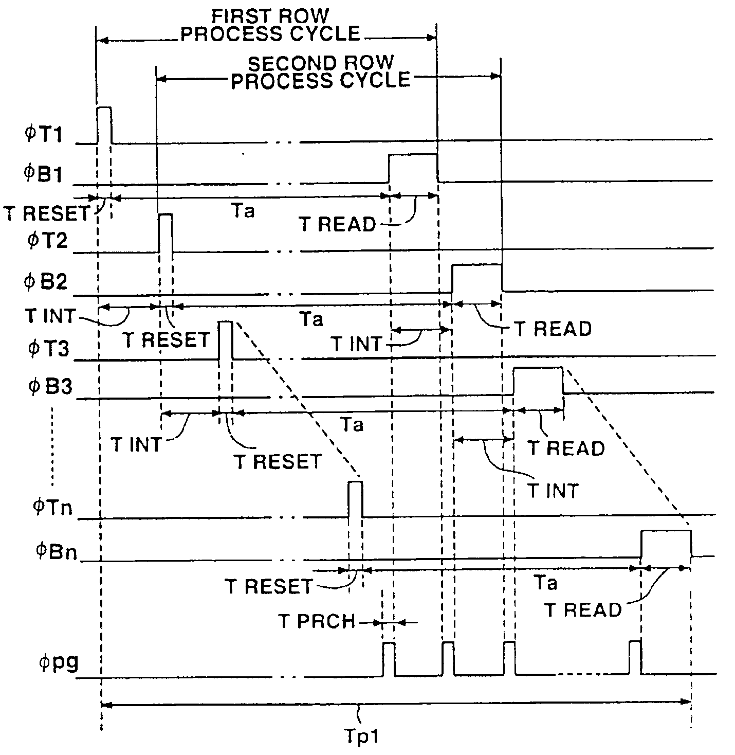
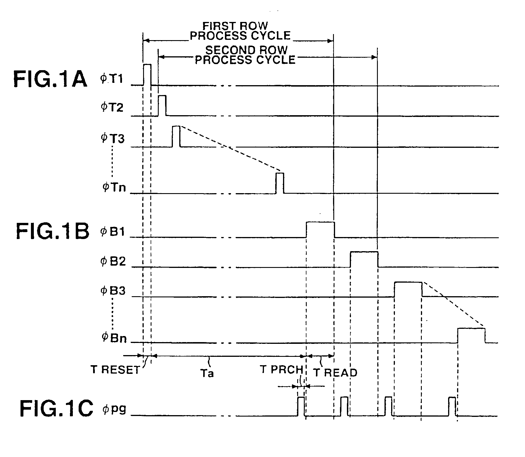
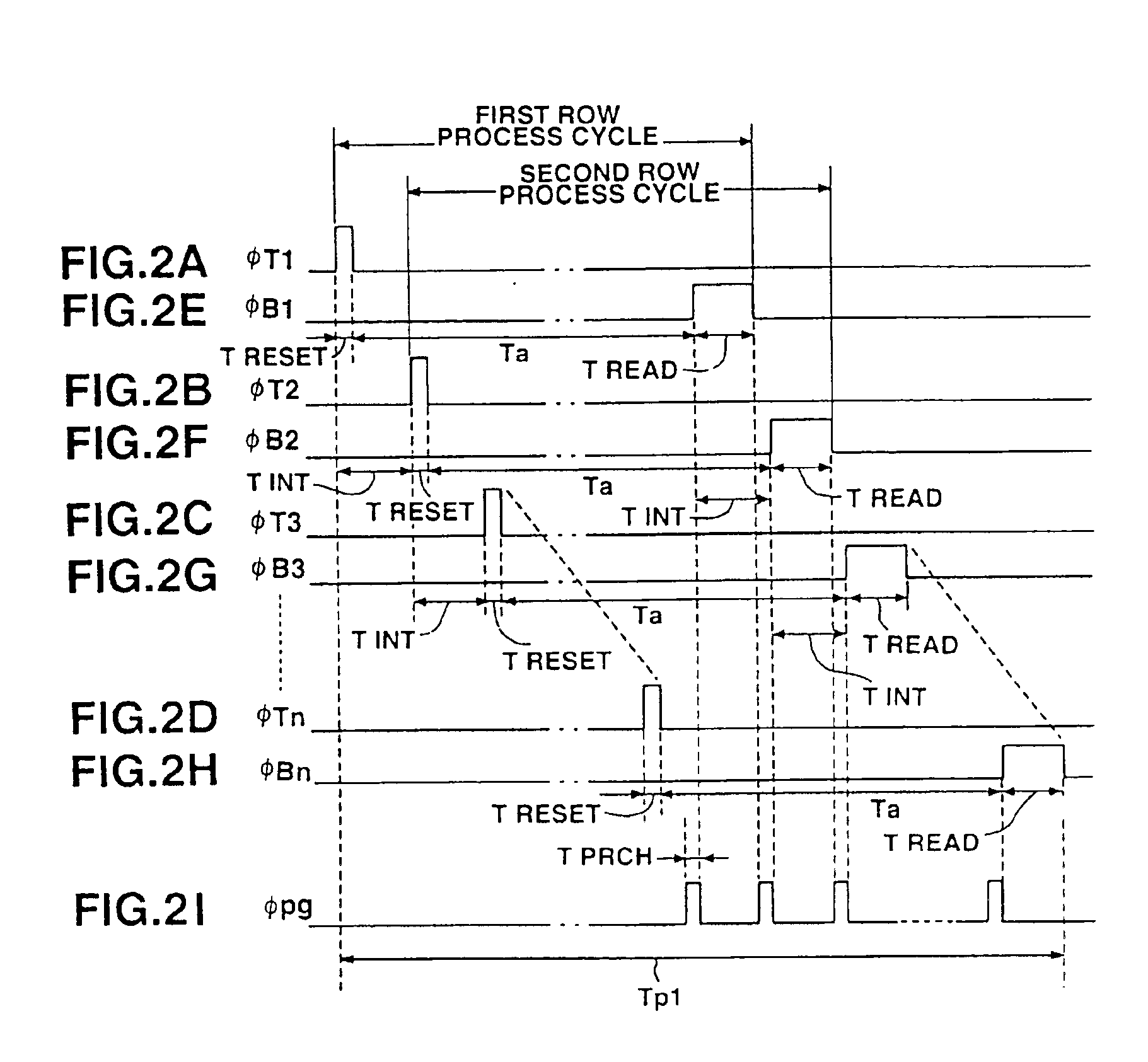
The second embodiment produces an advantage over the first embodiment as described below. Specifically, in the first embodiment, the interval among the reset pulse, the read pulse and the pre-charge pulse is set at the first pulse interval Tint, which is equal to the sum of the read period Tread and the pre-charge period Tprch, so as to prevent the read period for each row and the pre-charge period from overlapping in time with each other. However, if the charge accumulating period Ta is shortened so as to start the reading operation before completion of the reset operation for all the rows, it is possible for the reset period Treset for each row to overlap in time with the pre-charge period Tprch or with the read period Tread, making it impossible to perform reading accurately. Therefore, in the first embodiment, it is necessary to start the pre-charge operation and the read operation after completion of the reset operation for all the rows. This brings about a problem that it is i...

third embodiment

The third embodiment is directed to a drive control method in the processing (preparatory processing) for obtaining an optimum sensitivity set value that is changed in accordance with various conditions such as the brightness in the environment and the kind of the subject to be detected prior to the read operation (scanning operation) of the subject described in conjunction with the first and second embodiments of the present invention.

In the drive control method for the preparatory read processing according to the third embodiment of the present invention, the reset pulses φT1, φT2, φTn−1, φTn shown in FIGS. 4A to 4D are applied simultaneously to the top gate line 101 connecting the top gate terminals TG of the double gate type photosensors 10 in a row direction so as to initialize the double gate type photosensors 10 in all the rows.

These reset pulses φT1, φT2, . . . φTn−1, φTn are caused to simultaneously fall down to the lower level so as to terminate the reset period Treset. As...

fourth embodiment

The fourth embodiment is directed to a drive control method in the preparatory processing like the third embodiment.

In the drive control method for the preparatory read processing according to the fourth embodiment of the present invention, the reset pulses φT1, φT2, φTn−1, φTn shown in FIGS. 5A to 5D are successively applied to the double gate type photosensors 10 through the top gate line 101 connecting the top gate terminals GT in the row direction starting with the first row at the second pulse interval Tdelay shown in formula (5) so as to start the reset period Treset and, thus, to initialize the double gate type photosensors 10 for each row.

When each of the reset pulses φT1, φT2, φTn−1, φTn falls down to the lower level so as to terminate the reset period Treset, the charge accumulating period Ta is started. As a result, charge (hole) is accumulated in the channel region in accordance with the amount of light incident from the top gate electrode side of the double gate type ph...


PUM


Abstract

In a photosensor system formed of a photosensor array including a plurality of photosensors arranged in a two dimensional direction, the intervals of the reset pulse, read pulse and pre-charge pulse applied to each row of the photosensor array are respectively set equal to the sum of the reset period, the read period, and the pre-charge period. It follows that even where the read processing time of a single screen is shortened by allowing the processing cycles for the rows to partially overlap with each other, the reset period, the pre-charge period and the read period are prevented from being overlapped in time with each other, making it possible to perform the read operation accurately.

Description

CROSS-REFERENCE TO RELATED APPLICATIONSThis application is based upon and claims the benefit of priority from the prior Japanese Patent Applications No. 11-103413, filed Apr. 9, 1999; and No. 11-252108, filed Sep. 6, 1999, the entire contents of which are incorporated herein by reference.BACKGROUND OF THE INVENTIONThe present invention relates to a drive control method for a photosensor array including a plurality of photosensors arranged in a two-dimensional direction.In recent years, pickup devices such as an electronic still camera and a video camera have been prominently propagated. In such a pickup device, a solid state pickup device such as a CCD (Charge Coupled Device) is used as a photovoltaic device for converting the subject image into image signals. As known to the art, a CCD is constructed photosensors (light receiving elements) such as photodiodes and TFTs (Thin Film Transistors) that are arranged to form a matrix. The amount of electron-hole pairs (amount of charge) ge...

Claims


Application Information

Patent Timeline
Patent Type & Authority Patents(United States)
IPC IPC(8): H04N5/235H04N3/15H04N5/353
CPCH04N5/353H04N5/2351H01L27/1446H01L27/14643H01L27/14692H04N23/71H04N25/53H04N25/40H04N25/71
Inventor SUMI, SHINOBUNAKAMURA, YOSHIAKI
Owner CASIO COMPUTER CO LTD
Why Eureka
Try Eureka