
Method and system in a transceiver for controlling a multiple-input, multiple-output communications channel

Inactive Publication Date: 2005-02-22
GOOGLE TECH HLDG LLC
View PDF4 Cites 283 Cited by
  • Summary
  • Abstract
  • Description
  • Claims
  • Application Information

AI Technical Summary

Problems solved by technology

This works well with a high signal-to-noise ratio (SNR), but with a low SNR it boosts noise, which is not desirable.
While linear and non-linear receiver architectures can both be implemented to detect the multiple streams in noisy channels, in practical applications, noise in the channel will often require the use of non-linear receivers, which are more complicated and expensive to build.
Because transmitters in prior art systems lack data regarding the conditions of the composite channel, the performance of these systems cannot approach the Shannon bound for the MIMO channel.
Furthermore, the amount of data needed to describe a composite MIMO channel is large, which would consume a large percentage of channel capacity when communicated to the transmitter.

Method used


Image

  • Method and system in a transceiver for controlling a multiple-input, multiple-output communications channel
  • Method and system in a transceiver for controlling a multiple-input, multiple-output communications channel
  • Method and system in a transceiver for controlling a multiple-input, multiple-output communications channel

Examples


Embodiment Construction

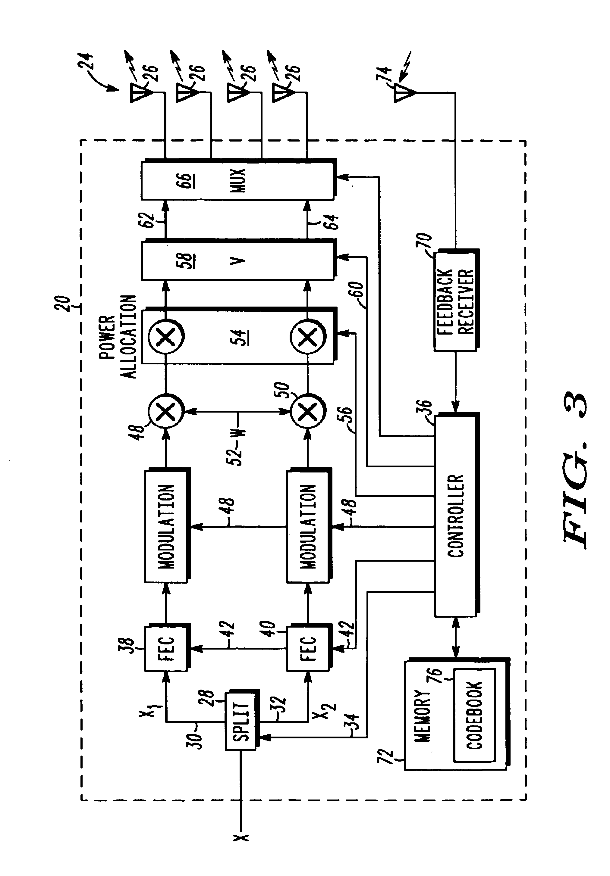
With reference now to FIG. 3, there is depicted a multiple-stream, multiple-antenna transmitter that may be used to implement the method and system of the present invention. As illustrated, transmitter 20 receives user data 22 and transmits user data 22 using antenna array 24, which comprises antenna elements 26.

User data 22 enters data splitter 28, which separates the user data stream into a plurality of data streams, such as data stream 30 and data stream 32. While two data streams are shown in FIG. 3, data splitter 28 may produce any number of data streams. Data splitter 28 splits data in proportion to control signal 34, which is produced by controller 36. For example, control signal 34 may specify a ratio of 2-to-1, wherein two bits are sent to data stream 30 and one bit is sent to data stream 32. This splitting ratio may specify an equal number of bits on both streams, or all data bits are sent to one stream.

Data streams 30 and 32 output by data splitter 28 are input into error...


PUM


Abstract

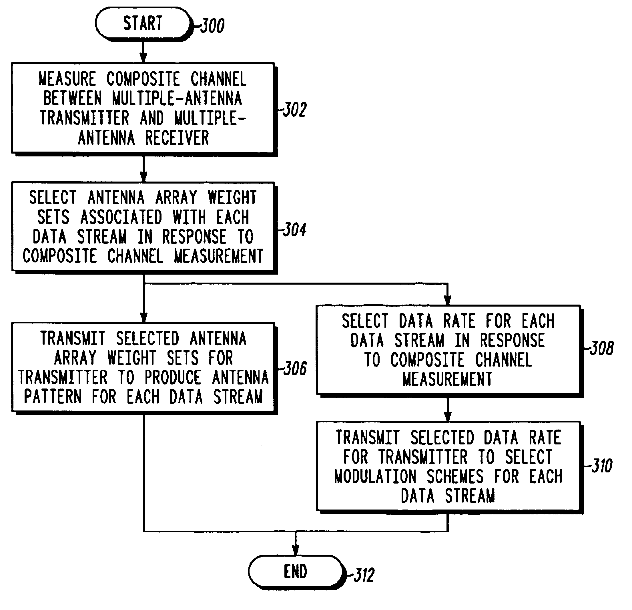
The present invention makes it possible to increase a data rate between a transmitter and receiver using a multiple-input, multiple-output radio frequency channel. A multiple-stream, multiple-antenna receiver measures a composite channel between a multiple-antenna transmitter and a multiple-antenna receiver to produce a composite channel measurement. The receiver selects a plurality of antenna array weight sets for use in the multiple-antenna transmitter in response to the composite channel measurement, where each antenna array weight set is associated with one of multiple data streams. Information describing the plurality of antenna array weight sets for use in the multiple-antenna transmitter are then transmitted.

Description

FIELD OF THE INVENTIONThe present invention is related in general to communication systems, and more particularly to a method and system for controlling the transmitting and receiving of multiple data streams in a multiple-input, multiple-output communications channel.BACKGROUND OF THE INVENTIONCommunication system designers are always looking for ways to increase the capacity of a communications channel between a transmitter and receiver. A communications channel may be defined as a system that transmits a sequence of symbols from one point to another. For example, a cellular communications system includes a channel for wirelessly transmitting a sequence of symbols that represent voice or data, back and forth between the telephone system and subscriber unit. An increase in the capacity of this channel means an increase in the rate of transmitting symbols. And when more symbols are transmitted in the same amount of time, voice can sound better, and it may take less time to transfer ...

Claims


Application Information

Patent Timeline
IPC IPC(8): H04B7/04H04B7/06H04B7/08H04J99/00
CPCH04B7/0417H04B7/0634H04B7/0639H04B7/0842H04L25/021H04L25/0248H04L25/03159H04L25/0204H04B7/0443H04L2025/03802H04L25/0228H04L2025/03426H04B7/06
Inventor PAUTLER, JOSEPH J.ROHANI, KAMYARHARRISON, ROBERT M.
Owner GOOGLE TECH HLDG LLC
Learn More