Initialization of wireless-controlled lighting systems

a wireless control and lighting system technology, applied in the field of wireless control of lighting systems, can solve the problems of limiting the types of new and replacement limiting the power consumption of any battery-powered device in the system (such as remote control), and limiting the range of lighting units that can be incorporated into the system. , to achieve the effect of widening the range of lighting units and simplifying the system

Inactive Publication Date: 2005-02-22
KONINK PHILIPS ELECTRONICS NV
View PDF6 Cites 168 Cited by
  • Summary
  • Abstract
  • Description
  • Claims
  • Application Information

AI Technical Summary

Benefits of technology

It is an object of the invention to provide a method which avoids the foregoing disadvantages.
The method is utilized to initialize both remote controls and other system components. Because the ID codes allocated to the system components are stored in the control master, reconfiguration of the system is simplified if the remote is lost or becomes inoperable. Also, an open standard, e.g. Zigbee, may be used for the communication protocol, thus widening the range of lighting units that can be incorporated into the system.

Problems solved by technology

Additionally, power consumption by any battery-powered devices in the system (such as remote controls) should be low to maximize battery life.
Further, the system must be capable of unambiguously controlling selected lighting units in the system and of incorporating lighting units which are later added to the system.
This limits the types of new and replacement lighting units that can be incorporated into the system.

Method used


Image

  • Initialization of wireless-controlled lighting systems
  • Initialization of wireless-controlled lighting systems
  • Initialization of wireless-controlled lighting systems

Examples


Embodiment Construction

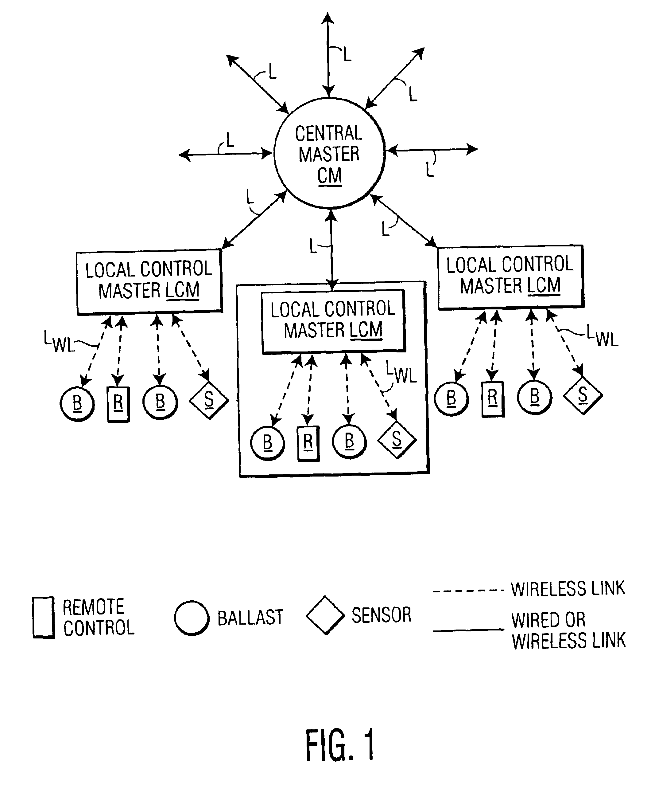
FIG. 1 illustrates an exemplary lighting-control system in which the invention is utilized. The system shown includes a number of local control masters LCM, each communicating with a central master CM via a wired or wireless link L. The choice of which type of link to be utilized for coupling each individual local control master to the central master is optional and depends on various factors. For example, wired links are commonly used in new lighting installations, while wireless links are commonly used in both retrofit and in new installations.

The central master CM functions to provide central control and monitoring of the entire lighting system (such as all rooms in a building or building complex), while each local control master LCM functions to provide control and monitoring within a local area (such as one or more rooms of a building). The local control masters LCM communicate via respective wireless links LWL to lighting-system components including lighting units B, sensors S...


PUM


Abstract

A method of initializing system components of a wireless-controlled lighting system. The system components include a remote control and a plurality of lighting units which communicate with a control master for the system via commonly-received radio communications. In order to become part of the system, each component transmits a respective request for initialization. A local control master for the system responds to each request, in turn, by allocating and transmitting a unique ID code for the requesting component. It then transmits a verify command to the requesting component which, if it has received the ID code, signals the user affirmatively.

Description

BACKGROUND OF THE INVENTION1. Field of the InventionThis invention relates to wireless-control of lighting systems and, in particular, to such control which is readily adaptable to changes in the system.2. Description of Related ArtWireless control of a lighting system provides many advantages besides the ability of remotely switching and dimming lighting units in the system. For example, such control provides a convenient way of setting up and making changes to a lighting system and of improving energy utilization. Features such as emergency lighting control can be added without making any wiring changes. Energy utilization by the system can be regulated by a program which can be readily modified to meet changing demands.In order for a wireless-controlled lighting system to be readily accepted by users, however, a number of considerations must be addressed. For example, the system should preferably be compatible with lighting control standards that are already in use, such as DALI ...

Claims


Application Information

Patent Timeline
Patent Type & Authority Patents(United States)
IPC IPC(8): H05B37/02H04Q9/00H04Q9/04
CPCH05B37/0245H05B37/0272Y10S370/908Y10S370/91H05B47/175H05B47/19
Inventor WANG, LING
Owner KONINK PHILIPS ELECTRONICS NV
Why Eureka
Try Eureka