Device for immobilizing a patient and compressing a patient's skeleton, joints and spine during diagnostic procedures using an MRI unit, CT scan unit or x-ray unit

a technology for immobilizing patients and patients, which is applied in the direction of patient positioning for diagnostics, applications, sofas, etc., can solve the problems of double the cost, patients regularly moving during the imaging process, and compromise the effectiveness of mri units, ct scan units and x-ray units as diagnostic tools

Inactive Publication Date: 2005-03-01
PORTAL
View PDF48 Cites 44 Cited by
  • Summary
  • Abstract
  • Description
  • Claims
  • Application Information

AI Technical Summary

Problems solved by technology

Such positioning of the patient compromises the effectiveness of the MRI unit, CT Scan unit and x-ray unit as diagnostic tools and causes various problems several of which are discussed below.
A significant problem for technicians operating MRIs, CT Scans and x-rays is that patients regularly move during the imaging process.
Such unwanted movements cause blurred or otherwise unreadable images and, consequently, require that new images be taken each time a patient's movements cause such problems.
It also doubles the costs of the diagnostic procedure which causes increased costs to health care providers and ultimately increases the overall costs of health care.
Another problem encountered by technicians employing a conventional MRI unit to image a patient's hips is that the patient's feet are mobile.
During imaging a patient may move his or her feet causing his or her hips to be unsuitably positioned for imaging.
Another substantial problem associated with placing patients in a relaxed and supine position during an examination of the skeleton, joints and spine using conventional MRI units, CT Scan units, or x-ray units is that the resulting diagnosis is often inaccurate.
Therefore, when an MRI unit, CT Scan unit or x-ray unit is used to diagnose injuries and disease in a patient's skeleton, joints and spine, their effectiveness as diagnostic instruments is compromised.
This occurs because the reduced pressures on the skeleton, joints and spine cannot accurately re-create the conditions existing in the skeleton, joints or spine when the patient is sitting, standing or walking.
This disassociation can be explained, in part, by the general inability of conventional MRI diagnosis techniques to allow the patient to be imaged while in a variety of positions, including the standing or sitting positions, to vary the intra-discal pressures and alignment of the vertebrae.
The relaxed supine position, in which all conventional MRIs of the lumbar spine are performed, is associated with the lowest intra-discal pressure, and is thus not a good position to provoke disc herniation, and is thus not the optimal position for accurate disc herniation diagnosis.
This same problem is experienced with the imaging and diagnosis of skeleton, joint and other spine injury or disease.
However, each one of these references suffers from one or more of the following disadvantages: the apparatus and method is awkward to operate which may cause the incorrect use of the apparatus or the failure to use the apparatus; the apparatus and method is not sophisticated enough to predictably and controllably exert pressure on the spine; the apparatus comprises materials which compromise or affect the accuracy or operation of an MRI unit; the apparatus and method do not immobilize the patient; the apparatus and method are not made for use in CT Scan units or x-ray units.
Thus there are multiple problems to be solved for the examination of a patient's body, skeleton, joints and spine with MRI units, CT Scan units and x-ray units.

Method used


Image

  • Device for immobilizing a patient and compressing a patient's skeleton, joints and spine during diagnostic procedures using an MRI unit, CT scan unit or x-ray unit
  • Device for immobilizing a patient and compressing a patient's skeleton, joints and spine during diagnostic procedures using an MRI unit, CT scan unit or x-ray unit
  • Device for immobilizing a patient and compressing a patient's skeleton, joints and spine during diagnostic procedures using an MRI unit, CT scan unit or x-ray unit

Examples


Embodiment Construction

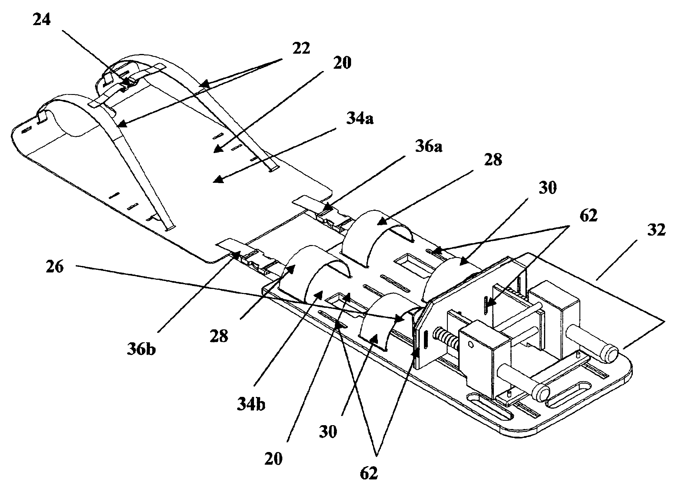
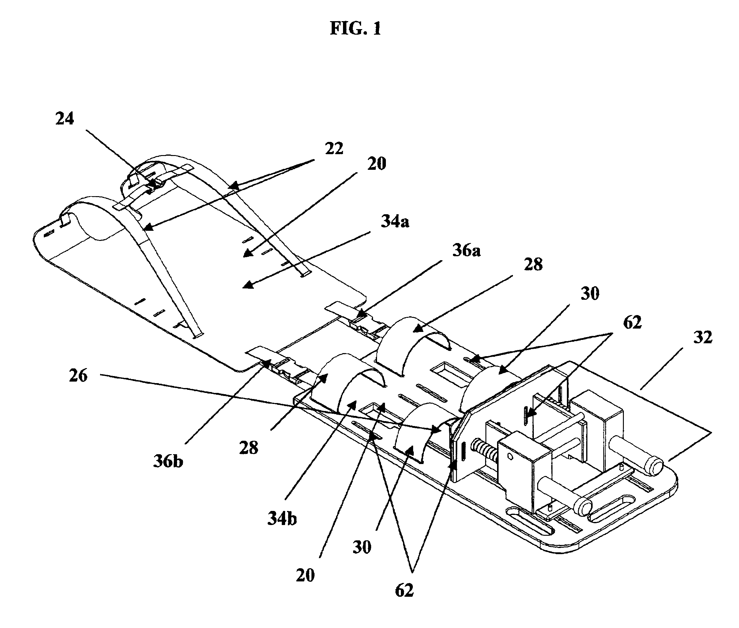
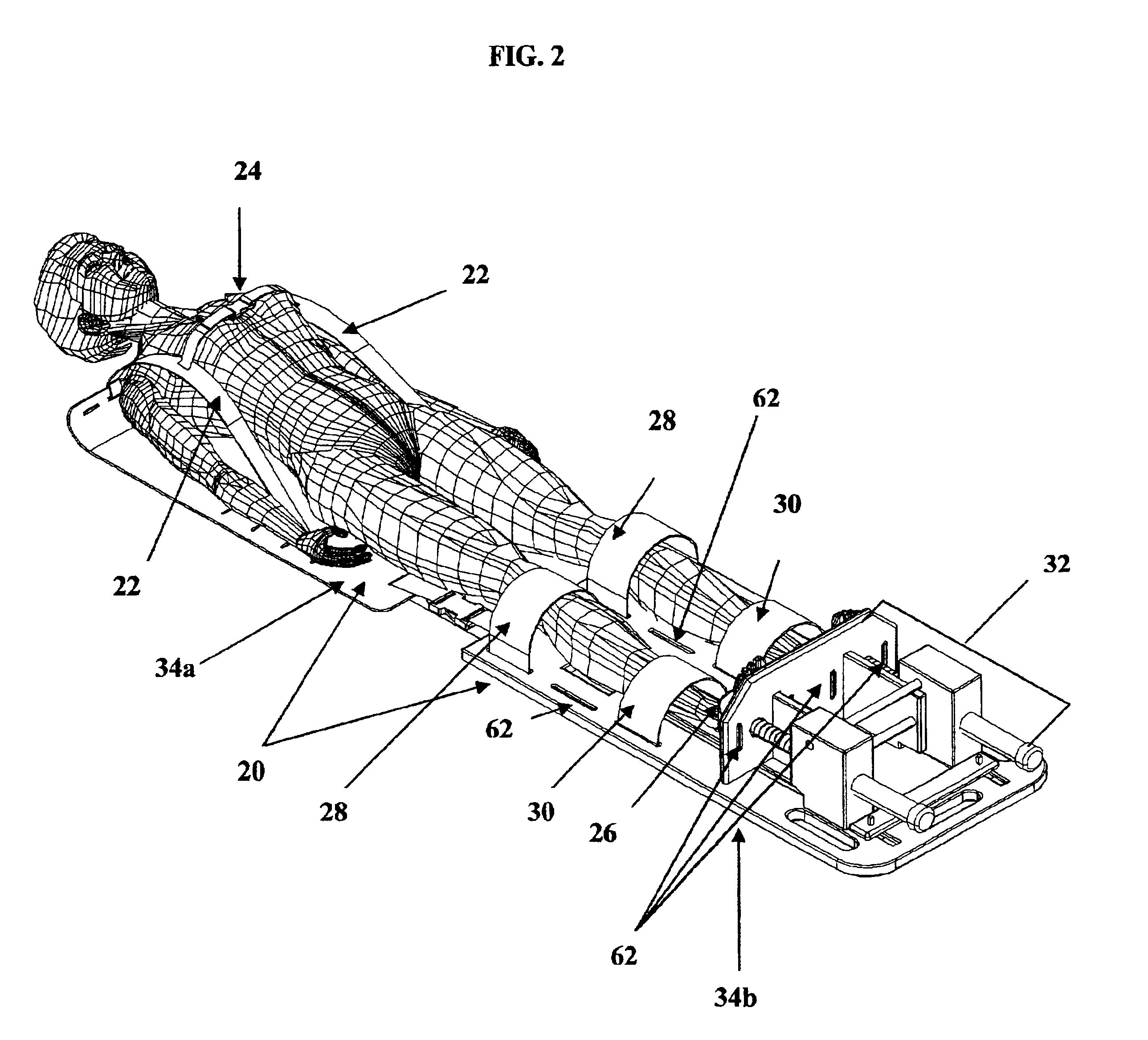
Referring to FIGS. 1, 2, 3 and 4, a patient resting surface 20 constructed in accordance with the present invention supports a patient in the supine position as shown in FIG. 2. Attached to the first end of the patient resting surface are shoulder immobilizers 22 and a chest immobilizer 24 to secure the patient's shoulders and chest to the patient resting surface as shown in FIG. 2. Attached to the second end of the patient resting surface are, knee immobilizers 28 and lower leg immobilizers 30 to secure the patient's knees and lower legs to the patient resting surface. Attached to the second end of the patient resting surface is a pressure creating apparatus 32 which exerts an upward pressure on the patient who is secured to the patient resting surface as shown in FIG. 2.

The invention will now be described in detail with reference to the attached drawings showing preferred and alternative embodiments of the present invention.

The present invention comprises a patient resting surface...


PUM


Abstract

The present invention relates to a device for use in diagnostic procedures using an MRI unit, CT Scan unit or x-ray unit, comprising a patient resting surface to which a patient's chest, shoulders, knees and lower legs are firmly, but comfortably secured, immobilizing the patient, a foot plate upon which the patient's feet rest or are secured, a pressure creating apparatus which applies a predictable, controllable and variable pressure to the patient's skeleton, joints and spine, and further immobilizes the patient who is secured to the patient resting surface and foot plate with immobilizers, an anchor securing the pressure creating apparatus to the second end of the patient resting surface.

Description

CROSS-REFERENCES TO RELATED APPLICATIONS(None)STATEMENT REGARDING FEDERALLY SPONSORED RESEARCH OR DEVELOPMENT(None)REFERENCE OF A “MICROFICHE APPENDIX”(None)BACKGROUNDThe present invention relates to a device for diagnostic purposes for use with imaging technologies such as Magnetic Resonance Imaging (“MRI”) Computerized Tomography (“CT Scan”) or x-rays.Traditionally, when a patient is examined using either a conventional MRI unit or a CT Scan unit, and regularly when a patient is examined using an x-ray unit, the patient is placed in a supine, relaxed and mobile position. Such positioning of the patient compromises the effectiveness of the MRI unit, CT Scan unit and x-ray unit as diagnostic tools and causes various problems several of which are discussed below.A significant problem for technicians operating MRIs, CT Scans and x-rays is that patients regularly move during the imaging process. Such unwanted movements cause blurred or otherwise unreadable images and, consequently, req...

Claims


Application Information

Patent Timeline
Patent Type & Authority Patents(United States)
IPC IPC(8): A61F5/37A61B6/04A61B5/055A61G1/01A61G1/00A61G1/044A61G1/048
CPCA61B6/0421A61F5/37A61B5/0555A61B5/4528A61G1/048A61G1/01A61G1/044A61B5/055A61B5/702
Inventor CARTER, CLAYTON REEDHICKEN, GREGORY JON
Owner PORTAL
Why Eureka
Try Eureka