Transport system for cargo containers, in particular for baggage containers

a technology for transportation systems and containers, applied in the field of transportation systems for cargo containers, can solve the problems of slowing down the speed by which containers are transported, containers have to be synchronized with spacing, and absence of discrimination, so as to reduce the distance between successive containers, increase the transport speed, and the effect of ensuring the safety of passengers

Inactive Publication Date: 2005-03-01
SIEMENS AG
View PDF13 Cites 8 Cited by
  • Summary
  • Abstract
  • Description
  • Claims
  • Application Information

AI Technical Summary

Benefits of technology

The present invention resolves prior art problems by providing an unloading device that includes a track which is suitably configured to implement a tilting of the container to be unloaded. In this way, the containers can pass through the unloading station without decrease in the transport speed. The engagement between the couplers and the containers can be controlled individually so that a discrimination of containers is possible. In other words, through control of the operation of the couplers, a container is able to move through the unloading station uninhibited, i.e. without being tilted, or the container is acted upon by the unloading device for tilting while still being advanced at the conveying speed.
According to another feature of the present invention, the container has a coupler-distal edge which is supported on the driven conveyor while the container is elevated from the other conveyor by the unloading device. In this way, it is possible to maintain the conveying speed and to transport the cargo container through the unloading station, without a need for an additional drive. It is only required to provide the tilting motion for the container, if the container is intended for emptying.
According to another feature of the present invention, the unloading device may include a plurality of vertically revolving rollers at a coupler-distal side wall of the unloading device in parallel relationship to the driven conveyor for preventing the container from slipping off on the side, where the edge of the container is supported on the conveyor, i.e. when the container assumes the tilted position. As an alternative, it is also possible to provide a vertical belt at the coupler-distal side wall of the unloading device in parallel relationship to the driven conveyor to support the container. When operated at a same speed as the driven conveyor, the vertical belt provides an additional drive for the container in the unloading station.
A transport system according to the present invention has many advantages. The tilting process can be added randomly to realize an elevation of a container while its further advance is executed at same speed. This operation is completely independent from any distance between the containers. In other words, as the plurality of containers approach the unloading station, selection can be made which of the containers is to be tilted and which should remain flat on the conveyors. This selection can be carried regardless whether the transport speed of the containers is fast or slow and whether the distance between the containers is small or large. As a consequence, the throughput remains unaffected and can even be enhanced through increase of the transport speed and decrease of the distance between successive containers. The provision of carriages to support the couplers does not adversely affect the overall throughput, because the overall dimension of the carriages is significantly smaller than the dimension of the containers so that a sufficiently large number of carriages can be made available. The tilting operation can be implemented with a minimum of parts so costs can be minimized, rendering the overall transport system cost-efficient. As the kinematics of the tilting mechanism is suited to the kinematics of the container, the container can advance uninhibited and without positional constraints onto the tilting mechanism. The translational energy of the container can be exploited for the tilting motion so as to eliminate the need for a separate energy transmission. The tilting operation can also be implement in a harmonic motion with little noise and little wear.

Problems solved by technology

A drawback of this process is the absence of any discrimination as to which of the containers should, in fact, be tilted and which containers should remain undisturbed.
This process has the drawback that the containers have to be synchronized with the spacing between the restraining elements.
Also this option results in a slow down of the speed by which the container is transported and thus in a decrease of the throughput.

Method used


Image

  • Transport system for cargo containers, in particular for baggage containers
  • Transport system for cargo containers, in particular for baggage containers
  • Transport system for cargo containers, in particular for baggage containers

Examples


Embodiment Construction

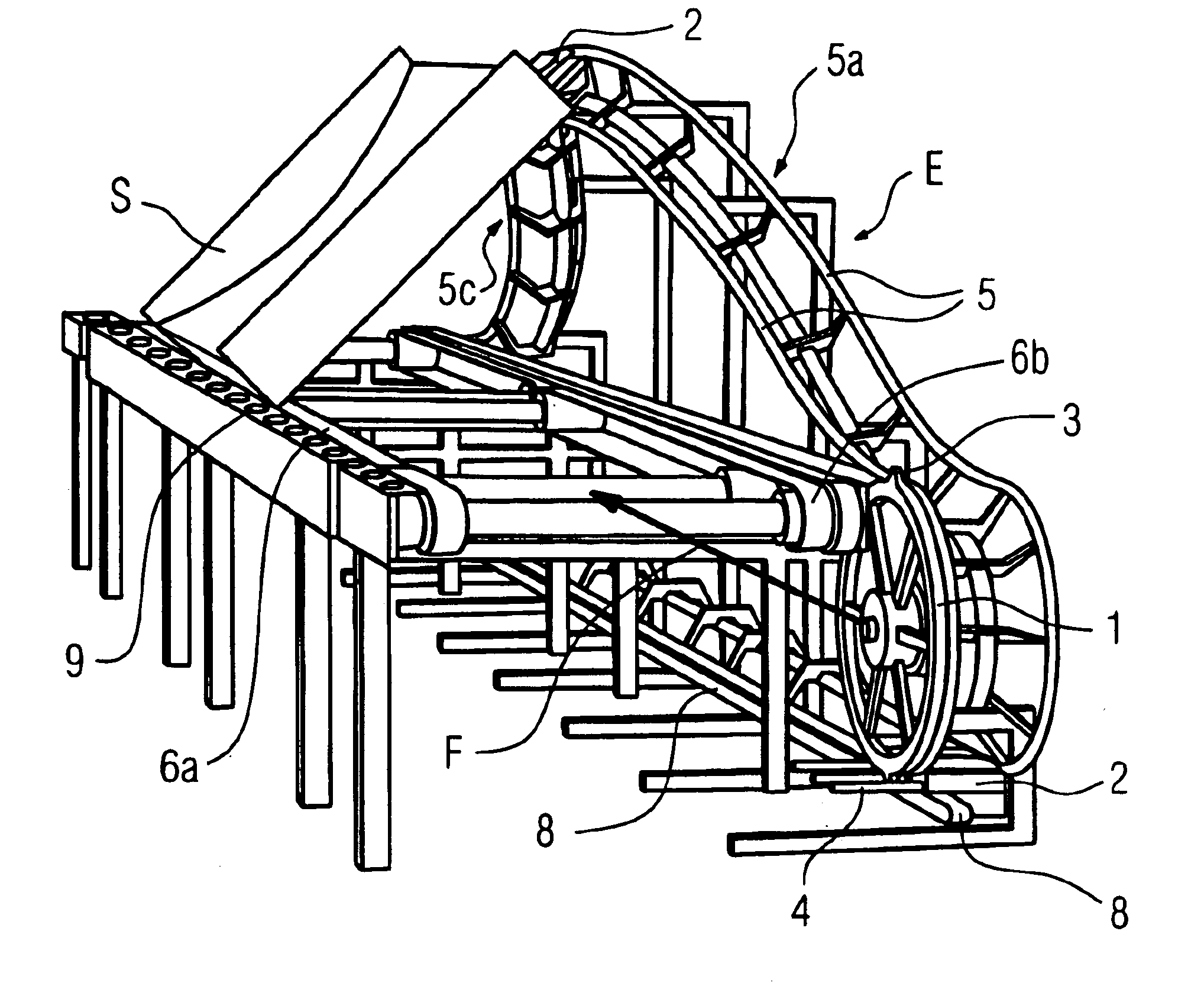
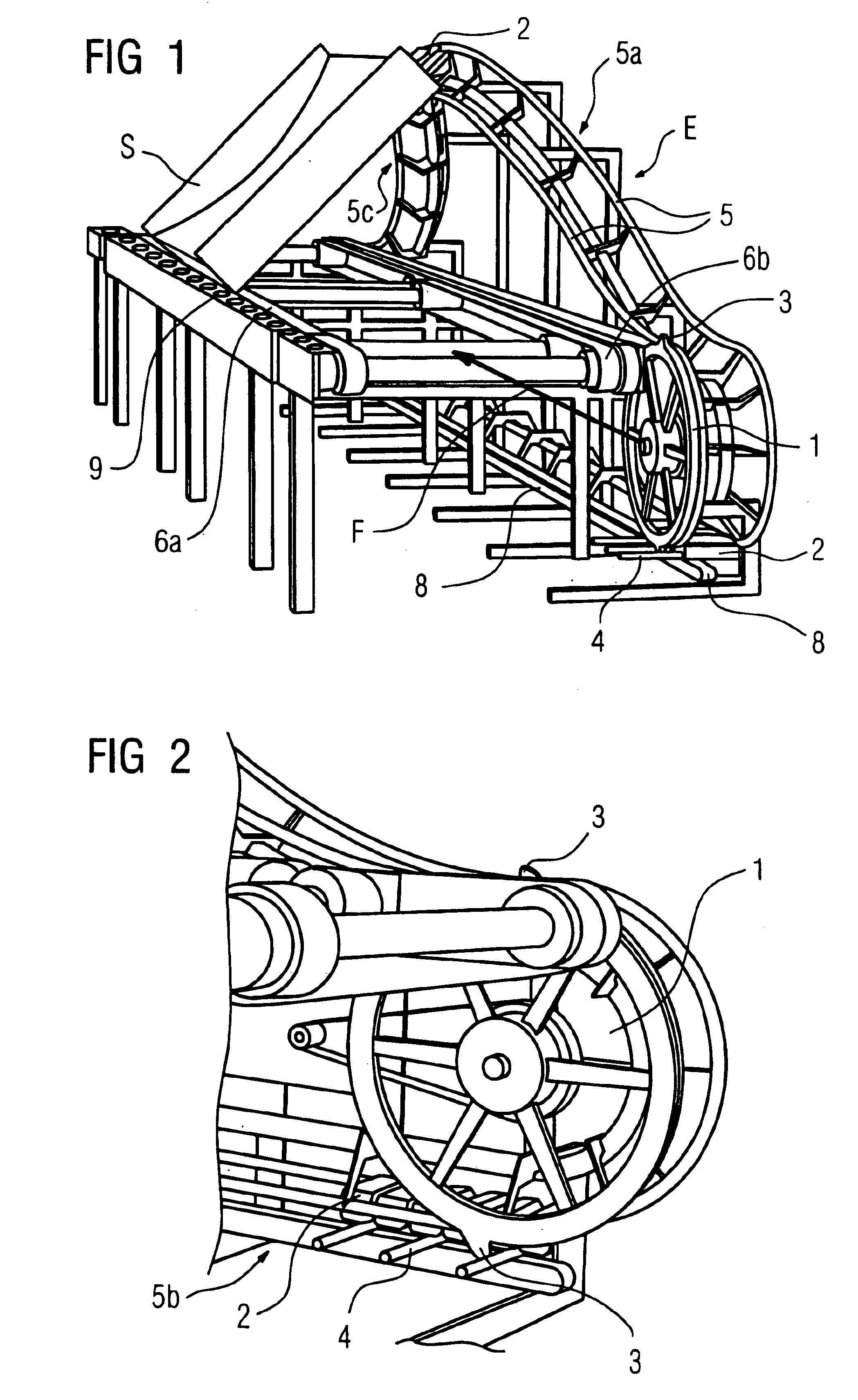
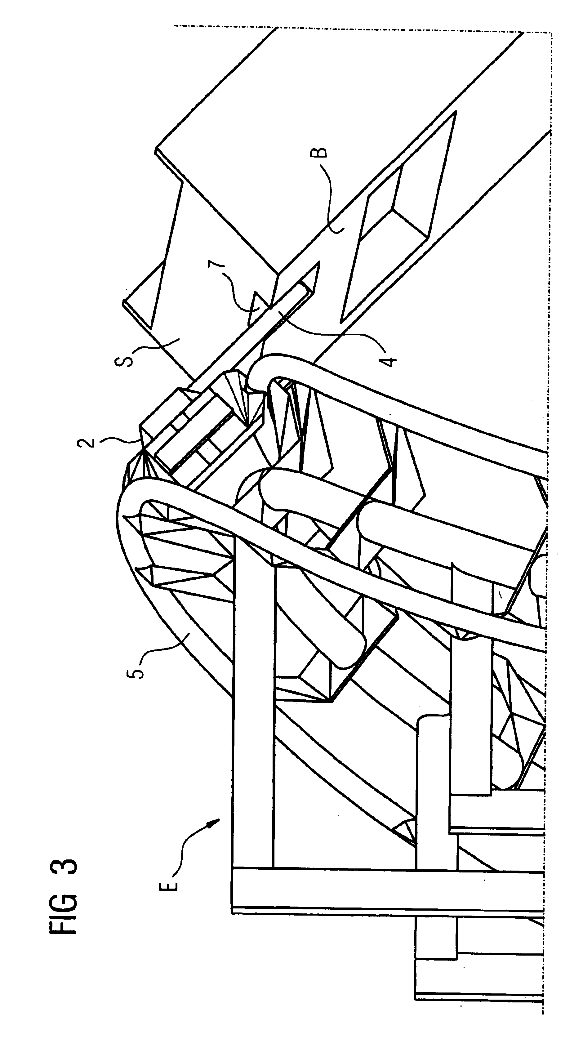
Throughout all the Figures, same or corresponding elements are generally indicated by same reference numerals. These depicted embodiments are to be understood as illustrative of the invention and not as limiting in any way. It should also be understood that the drawings are not necessarily to scale and that the embodiments are sometimes illustrated by graphic symbols, phantom lines, diagrammatic representations and fragmentary views. In certain instances, details which are not necessary for an understanding of the present invention or which render other details difficult to perceive may have been omitted.

Turning now to the drawing, and in particular to FIG. 1, there is shown a simplified perspective view of a transport system according to the present invention for unloading a cargo container S which can be made of a dimensionally stable plastic material. The container S has a cup-shaped surface for placement of an article to be transported, e.g. baggage, and is transported in convey...


PUM


Abstract

A transport system for cargo containers includes at least two spaced-apart conveyors for transporting a cargo container in conveying direction along a substantially horizontal transport path, wherein at least one conveyor is driven. Disposed to the side of the other conveyor is an unloading device for discharging the cargo by tilting the container. The unloading device includes a track with a looped section, and a plurality of couplers constructed for engagement with the containers at a leading end of the looped section, as viewed in conveying direction, and for disengagement from the containers at a trailing end of the looped section. The looped section is spatially configured to tilt the container as a one of the couplers engages the oncoming container on one side adjacent the other conveyor and is guided along the track.

Description

CROSS-REFERENCES TO RELATED APPLICATIONSThis application claims the priority of German Patent Application, Serial No. 102 36 168.1, filed Aug. 7, 2002, pursuant to 35 U.S.C. 119(a)-(d), the disclosure of which is incorporated herein by reference.BACKGROUND OF THE INVENTIONThe present invention relates, in general, to a transport system for cargo containers, in particular for baggage containers.Transport systems are oftentimes used in airport environment to transport checked bags along a conveyor path and to sort them for transfer to the destination. The baggage is hereby transported in containers and transferred to the destination by retrieving respective information inputted in an administrator. Unloading of the container, i.e. separating the content (baggage) from the container at the destination or transfer to a conveyor leading to the destination can be realized in many different ways.According to the so-called “dynamic forced emptying process”, the container is emptied by routi...

Claims


Application Information

Patent Timeline
Patent Type & Authority Patents(United States)
IPC IPC(8): B65G47/74B65G47/94B65G47/96
CPCB65G47/965
Inventor BRIXIUS, WOLFGANGGRAFER, DOMINIKHOENE, ALBRECHT
Owner SIEMENS AG
Why Eureka
Try Eureka