
Optical symbologies imager

a symbologie and optical technology, applied in the field of imagers, can solve the problems of inability to scan 2d symbologies, inability to accept imagers by end users, and inability to be commercially viable, and achieve the effect of eliminating variation in the position of imagers, achieving fast and accurate illumination and focusing steps, and eliminating the variation of imagers

Inactive Publication Date: 2005-03-01
MICROSCAN SYSTEMS
View PDF17 Cites 82 Cited by
  • Summary
  • Abstract
  • Description
  • Claims
  • Application Information

AI Technical Summary

Benefits of technology

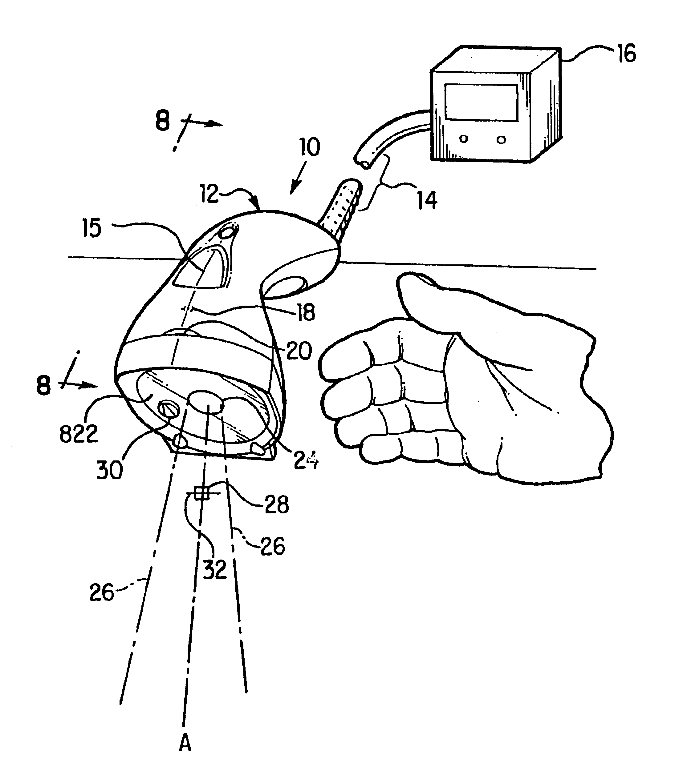
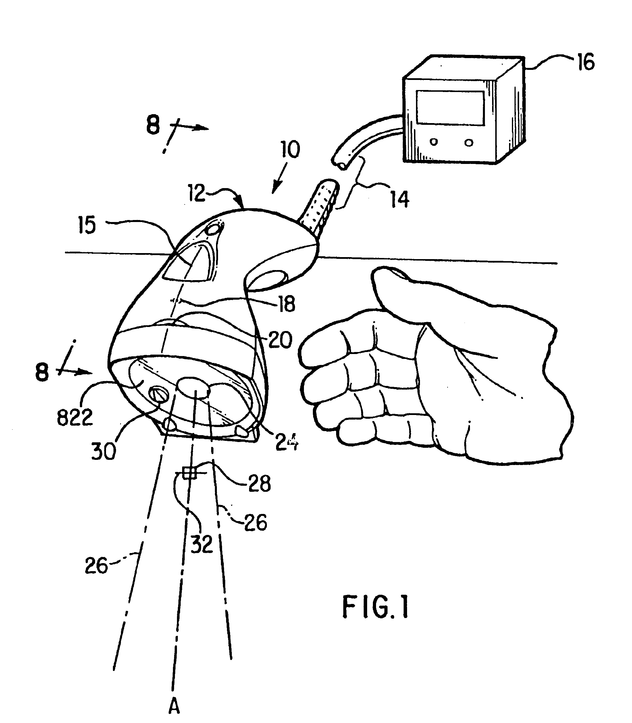
These and other deficiencies of the prior art are addressed by the present invention which is directed to a hand-held imager which is capable of reading both linear one dimensional codes and two dimensional symbologies, which can perform illuminating and focusing steps quickly and accurately so as to eliminate variation in the position of the imager relative to the code, and which can operate in an environment where the imager is preferably positioned anywhere from substantially 1.5 inches to 16 inches from the targeted code.
The hand-held imager of the present invention can perform omnidirectional coded symbology reading for both linear and two-dimensional symbologies over relatively long working distances. The imager includes an imaging system having a focusing system, an illumination system, and a two-dimensional photodetector which forms an image of the bar code. After achieving targeting of the coded symbology, the reader of the present invention adjusts illumination and then the focus between multiple different focuses, and utilizes a portion of the two-dimensional photodetector to determine the optimum focus. Upon the determination of optimum focus, the focusing system is configured at the optimum focusing configuration established in the initial focusing step, and an image is created using the entire two-dimensional photodetector.
A targeting system visually assists the user to position the reader so that the coded symbology, being targeted, is within the field of view of the reader. The reader has two types of illumination, one for symbologies which are close to the reader, and a second type of illumination for symbologies which are farther from the reader. The two-dimensional photodetector may be employed to determine the optimum illumination.
Another object of the present invention is to provide a hand-held reader which can perform an imaging operation in a range between 1.5 inches and 16 inches to the coded symbology for typical hand-held use, but may have both higher and lower distance limits.
Still another object of the present invention is to provide a hand-held reader which utilizes a two dimensional sensor to facilitate focusing and illumination adjustment.
Yet another object of the present invention is to provide a hand-held reader which utilizes a two dimensional sensor to facilitate focusing and illumination adjustment, where only a small portion of information received by the two dimensional sensor is used, to thereby speed processing.

Problems solved by technology

While it may be possible to create an imager which can perform all of the desired functions, if the imager does not operate in a manner the user finds comfortable and sufficient, then the imager will not be accepted by end users and will not be commercially viable.
For example, if the imager cannot perform the focusing quickly enough, then variations in the position of the scanner, due to the inability of the user to hold the imager steady, will create problems which cannot be easily overcome.
Scanners which have been designed to read linear, or one dimensional, codes are, for the most part, incapable of scanning 2D symbologies.
Most conventional scanners may find it difficult to read symbologies which have been etched directly onto a product.

Method used


Image

  • Optical symbologies imager
  • Optical symbologies imager
  • Optical symbologies imager

Examples


first embodiment

the focusing disk 94, shown in cross-section in FIG. 4, is shown in greater detail in FIG. 5a. The disk 94 has a series of different thickness optical positions 132. The thickness of the optical positions 132 is varied to focus the objective lens 92 onto the CCD detector 93 during image capture. The illustrated embodiment shows twelve optical positions 132 which thereby provide twelve potential focus ranges. A positional encoding strip 134 is provided on the disk 94 so that the position of the disk can be tracked. However, it is noted that the invention could operate with at least two optical positions.

Referring to FIGS. 5b and 5c, planar and cross-sectional views of a second embodiment of the focusing disk 94 is shown. The second embodiment has eight optical positions 132 and further includes an outer circumferential wall 136 which provides additional structural support.

The CCD detector 93 is utilized to determine which optical plate 132, and therefore which focusing zone, is appro...


PUM


Abstract

A hand-held imager which is capable of reading both linear and two dimensional symbologies, which can perform focusing and illuminating steps quickly and accurately so as to eliminate variation in the position of the imager relative to the code becoming a negative factor, in which can operate in environment where the imager is anywhere from 1.5 inches to 16 inches from the code. The imager includes an imaging system having a focusing system, an illumination system, and a two-dimensional photodetector which forms an image of the coded symbology. After achieving targeting of the coded symbology, the scanning system adjusts the focus between multiple different focuses, and utilizes a portion of the two-dimensional photodetector to determine the optimum focus. Upon the determination of optimum focus, the focusing system is returned to the focusing configuration established in the initial focusing step, and an image is created using the entire two-dimensional photodetector. Optimum illumination is determined using the same two-dimensional photodetector.

Description

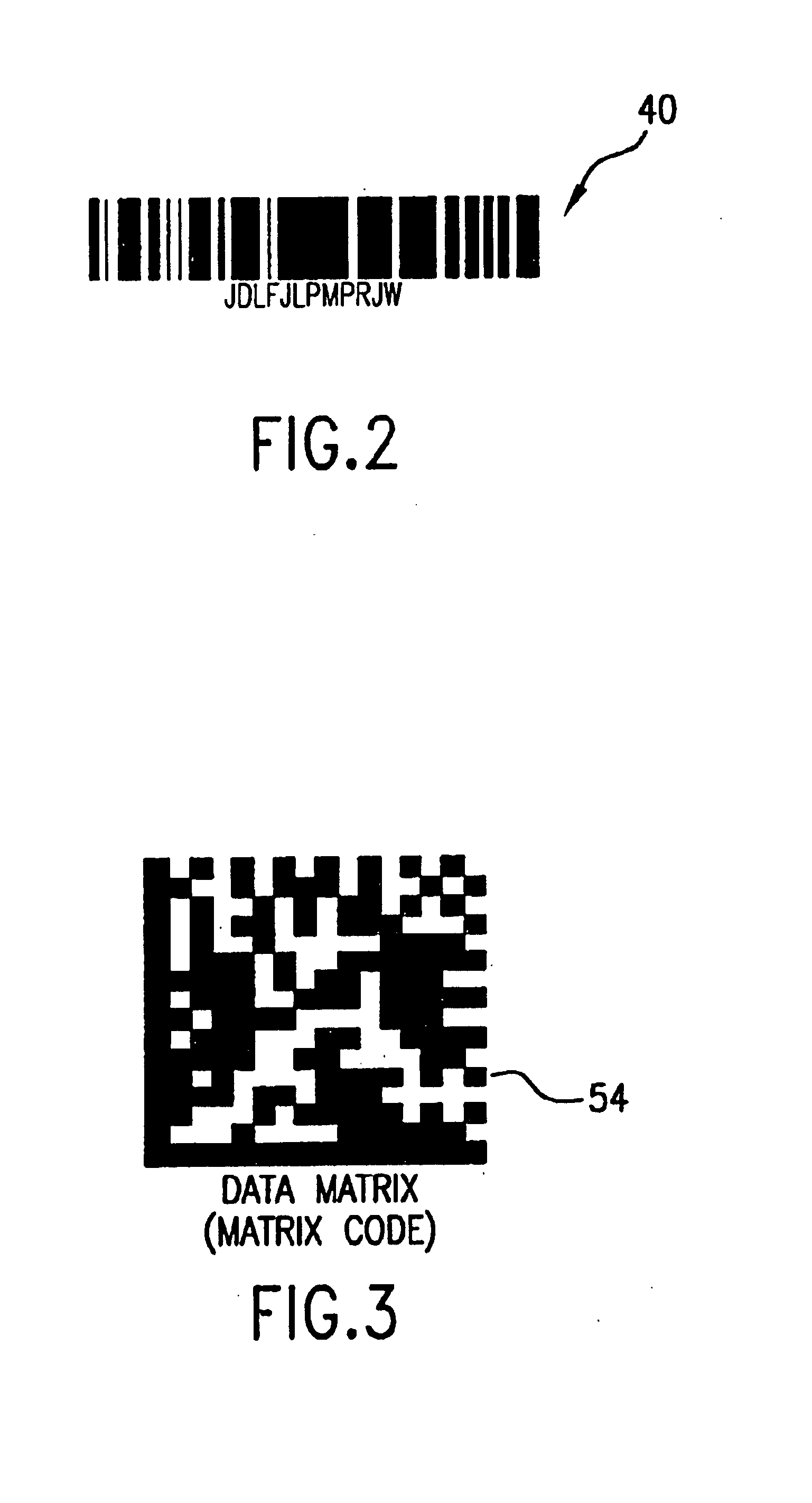
BACKGROUND OF THE INVENTION1. Field of the InventionThe present invention relates to an imager for reading optical symbologies such as traditional bar codes and 2D symbologies. More particularly, the present invention relates to a hand-held optical code imager which quickly and easily adjusts illumination and focus and has an preferred operating range of approximately 1.5 to 16 inches, however, the imager may have an operating range with both lower and higher limits, and still fall within the intended scope of the present application.2. Description of the Prior ArtThe use of bar codes has proliferated to the point where they are used in almost every industry to provide machine readable information about an item or product and to help track such items. Numerous different symbologies have been developed, such as one dimensional linear codes and 2D codes, such as Data Matrix. Typical linear codes comprise a series of parallel lines of varying thickness and spacing which are arranged in...

Claims


Application Information

Patent Timeline
Patent Type & Authority Patents(United States)
IPC IPC(8): G06K7/10
CPCG06K7/10811G06K7/10742
Inventor DOWLING, JOHN H.STERN, HOWARDMCKINLEY, HARRY R.MCKINLEY, PHILIP E.LEE, JASON J.FIGARELLA, LUIS ALBERTO
Owner MICROSCAN SYSTEMS
Learn More