Polyolefin connectors

a technology of polyolefin and connector, which is applied in the direction of fluid pressure sealing joints, hose connections, mechanical equipment, etc., can solve the problems of inability to meet the requirements of the application of the hose, the cost of forming the same to permit the connection to such fixtures or tanks, and the cost of such copper tubing and the cost of forming the same to permit the connection, etc., to achieve the effect of ensuring the performance integrity of the two-part tubing end cap

Inactive Publication Date: 2005-03-01
MERCURY PLASTICS LLC
View PDF54 Cites 44 Cited by
  • Summary
  • Abstract
  • Description
  • Claims
  • Application Information

AI Technical Summary

Benefits of technology

In accordance with the present invention, there is provided a method for processing polyethylene polymers which will enable a work piece to have a one-piece formed / shaped ends from a single piece of tubing.

Problems solved by technology

The cost of such copper tubing and the cost of forming the same to permit the connection to such fixtures or tanks is substantial.
All such processes have cost and performance drawbacks.
Moreover, a two-part tubing end cap or bulb sealing construction does not have the performance integrity or the expected useful life of the tubing itself.
In the spin welding technique, excessive clamping pressures may cause the loaded part to become dislodged or separated from the O.D. of the tubing and the interface of the parts provides a possibility of leakage.
Moreover, a flange formed to receive the washer may itself create a point of weakness if excessive clamping pressures are employed.
Further neoprene washers are known to deteriorate with age and temperature exposure.
A corresponding associated problem with the formation of the above-described male end of the polybutylene tubing, is the ability to bell an opposed end of the tubing, without any accompanying wall thickness compromise, which would make the product unsuitable for all plumbing applications, for which polybutylene has been approved, provided that a wall thickness can be maintained at 0.062″±0.010″, as defined by ASTM 3309.
While this approach will bell the tubing, it is incapable of reproducibly making tubing products with a constant wall thickness of 0.062″±0.010″ throughout the belled end, particularly in the neck region of the bell.
However, this shift in materials is not simple in that there are several processing changes which must be incorporated in order to fabricate acceptable parts.
For example, it is not possible to simply take a crosslinked polyethylene tube and mold it into a bulb end by taking the polybutylene technology taught in the prior art.
This is an inherent weak spot in the final product, and the industry has long sought to find a solution to the problem of developing a one-piece plumbing part made out of a thermoset plastic.

Method used


Image

  • Polyolefin connectors
  • Polyolefin connectors
  • Polyolefin connectors

Examples


Embodiment Construction

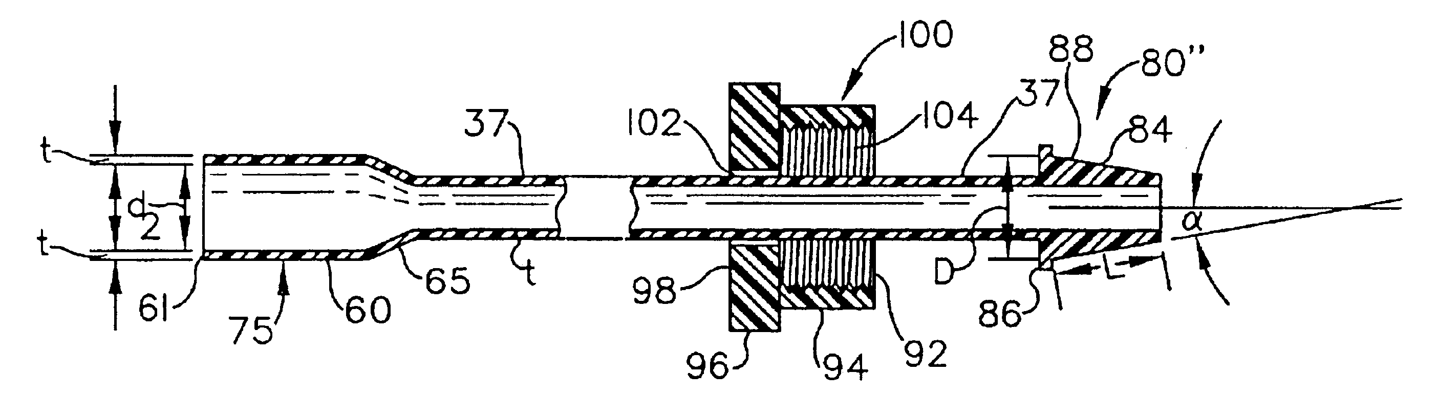
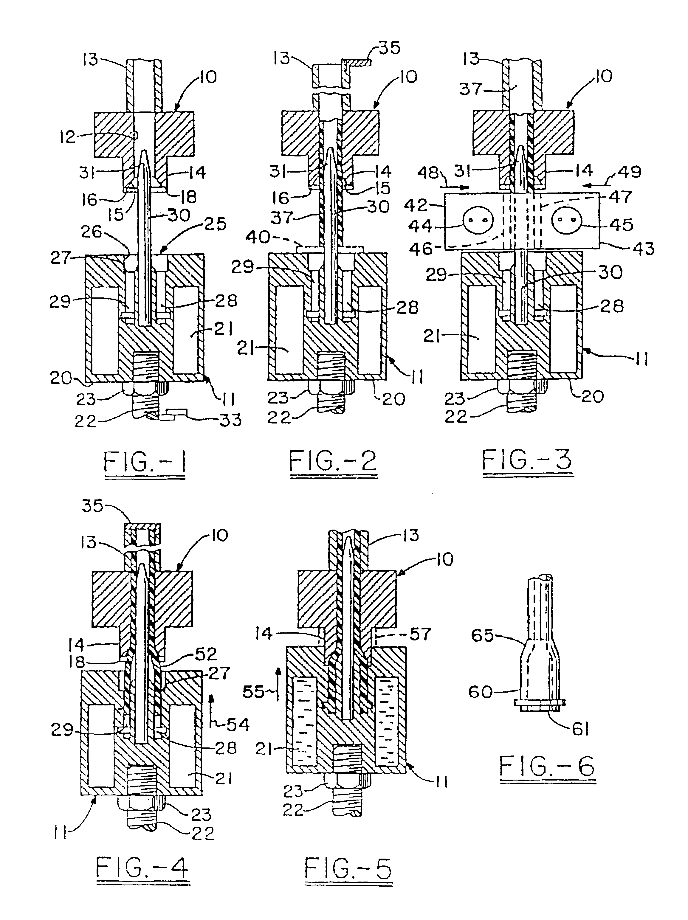
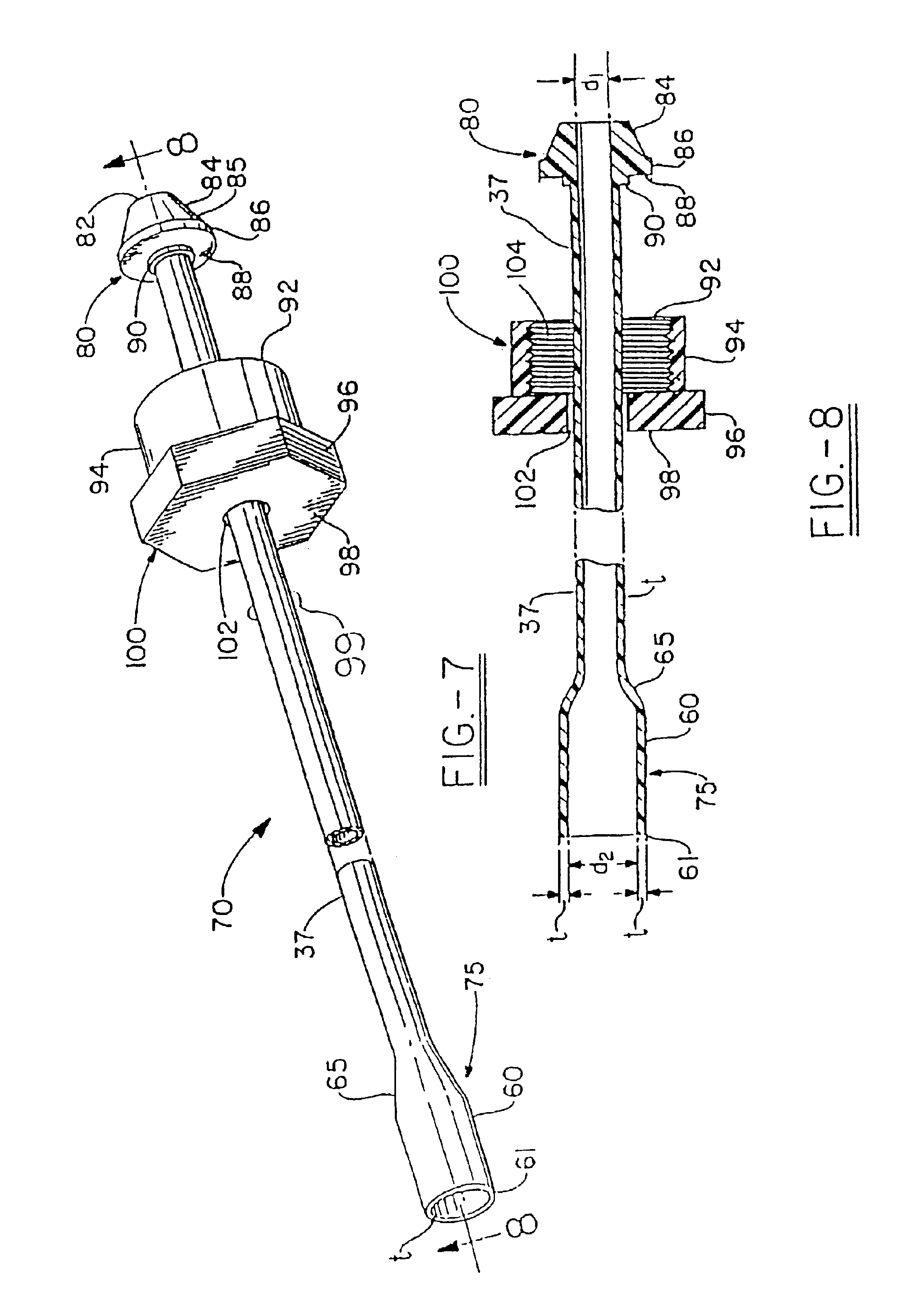
Referring now to the drawings wherein the showing are for purposes of illustrating the preferred embodiment of the invention only and not for purposes of limiting the same, the Figures show cut lengths of plastic tubing upon which various end configurations have been fabricated onto.

As seen in the Figures, the tubing comprises a top vertically fixed mold 10 and a vertically movable bottom mold 11. The top mold or die 10 includes a central bore 12 and a riser tube 13 secured to the top thereof having an I.D. the same as the I.D. of the bore 12. The lower surface of the top mold is provided with a cylindrical projection 14 projecting centrally therefrom. The lower end of the bore is provided with a conical flaring portion 15, the lower end of which is provided with a small radius seen at 16. Radially beyond such radius, the bore is terminated in an axially extending edge 18.

The bottom mold 11 includes a body 20 which may include an annular passage 21 for the circulation of cooling med...


PUM

PropertyMeasurementUnit
densityaaaaaaaaaa
densityaaaaaaaaaa
flexural modulusaaaaaaaaaa

Abstract

A one-piece polyolefin connector or polymeric blend connector with the characteristics of a polymer having the specific density of between 0.90 and 0.96 g/cc capitalizing on the aspect ratio of the connector and angularity of the sealing surface in combination for use in applications less physically demanding than those for use with crosslinked polyethylene material.

Description

TECHNICAL FIELDThe invention described herein pertains generally to a method for processing plastic tubing ends, particularly those of polyethylene, and more generically, polyolefins, and more particularly, medium density polyethylene and high density polyethylene, at times blended with polypropylene, or using homopolymer polypropylene. The method refers generally to belling and reforming tubing ends without compromising wall thickness, as well as the formation of sealing surfaces therefrom, thereby enabling the work piece to be suitable for plumbing applications. In one application of this invention, the technology will involve crosslinking to at least a limited degree, i.e., less than 10%, preferably less than 5%, and more preferably, less than 1%. In an alternative embodiment, the technology will eliminate this crosslinking step and result in a tubing end which is more flexible than polypropylene or crosslinked polyethylene, yet which will be suitable for use in low pressure, col...

Claims


Application Information

Patent Timeline
Patent Type & Authority Patents(United States)
IPC IPC(8): B29C57/00B29C57/04
CPCB29C57/00B29C57/04B29K2105/24B29K2023/0641B29K2023/06
Inventor ROWLEY, WILLIAM W.
Owner MERCURY PLASTICS LLC
Why Eureka
Try Eureka