Object detection apparatus and method

a technology of object detection and apparatus, applied in the field of multi-frequency sensing systems, can solve the problems of frequency dependence of material reflectivity, difficult to complete the characterization of this reflection from most real objects,

Inactive Publication Date: 2005-03-01
ELLISTAR SENSOR SYST
View PDF11 Cites 14 Cited by
  • Summary
  • Abstract
  • Description
  • Claims
  • Application Information

AI Technical Summary

Benefits of technology

For objects that are considered large relative to the wavelength of a respective electromagnetic wave, the average reflection in the direction of the incident wave's source is proportional to the object's cross section, even though it may vary by orders of magnitude with small changes in orientation and shape. The frequency dependence on material can be made dominant for these cases by suitable averaging of target reflections, and this enables the identification of target type through the use of multiple well-chosen radar frequencies.

Problems solved by technology

The complete characterization of this reflection from most real objects is an extremely difficult problem.
The permittivity is, however, a complex value having an imaginary part that leads to a frequency dependence of the material's reflectivity.

Method used


Image

  • Object detection apparatus and method
  • Object detection apparatus and method
  • Object detection apparatus and method

Examples


Embodiment Construction

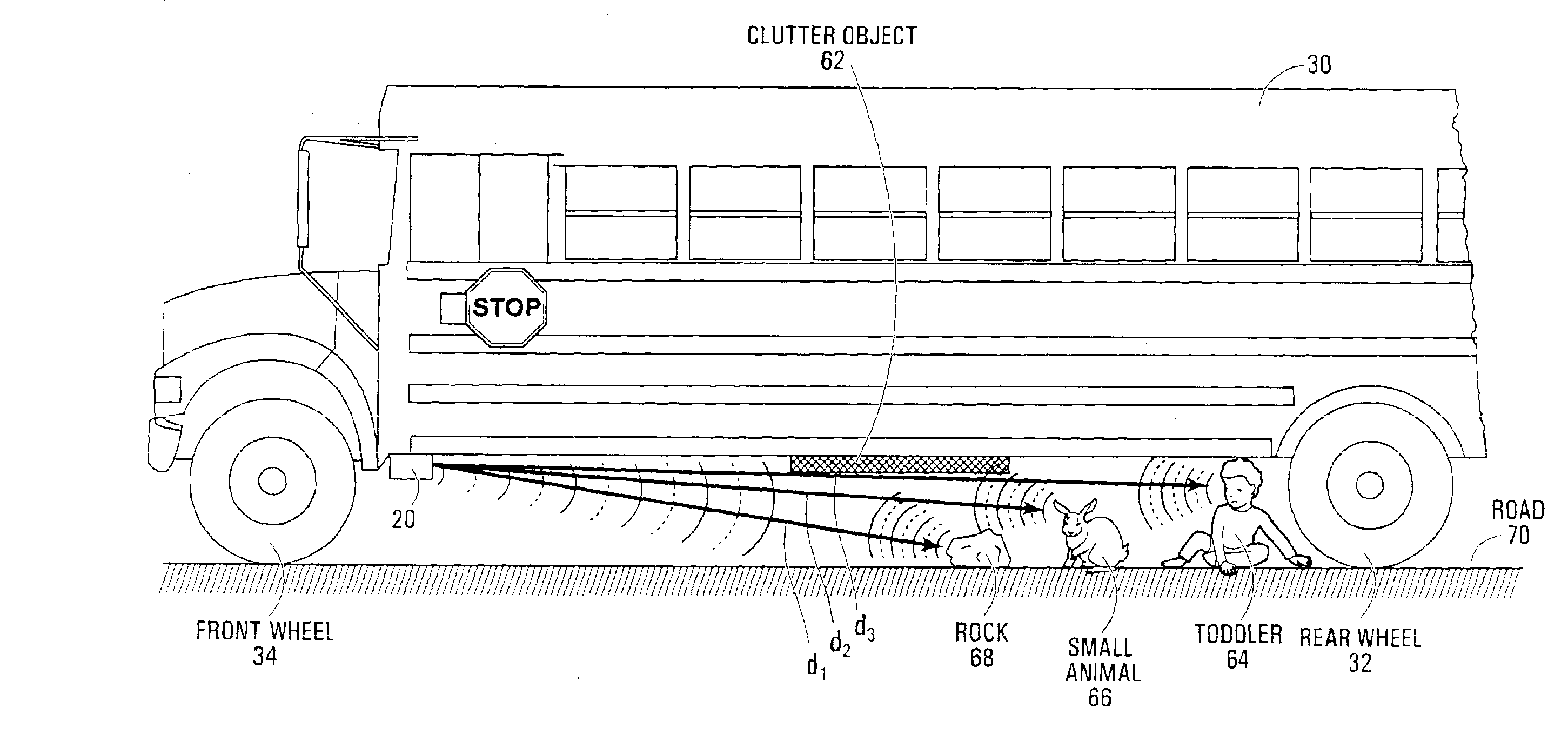
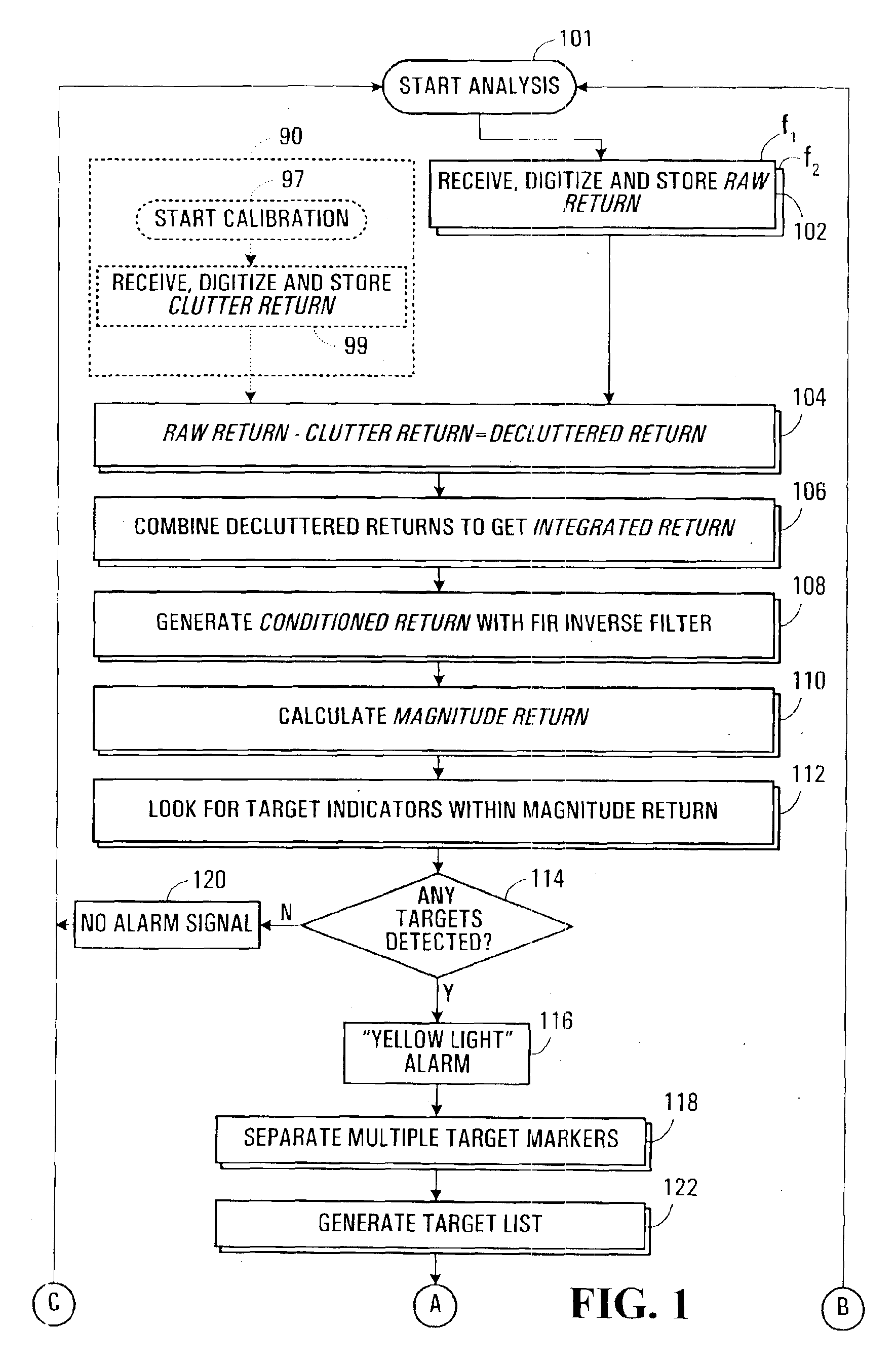
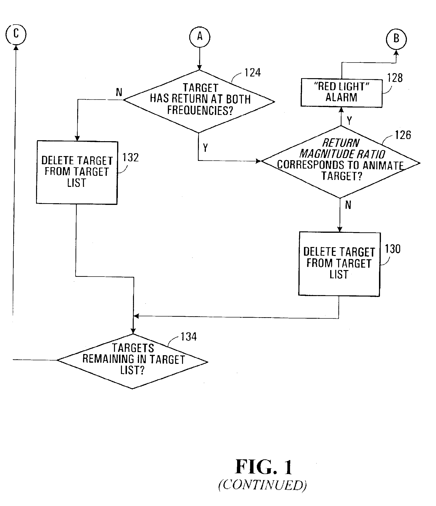
Referring now to FIG. 1, shown is a flow chart depicting a method of sensing according to an embodiment of the invention. As described above, the invention generally involves the use of at least two frequencies. In this very specific example embodiment of the invention, the sensing method is described using two radio frequencies f1 and f2.

The In-phase (I) and Quadrature (Q) channels of each of the radio frequencies f1 and f2 are also advantageously used according to this embodiment of the invention. The advantages of using the I and Q channels are described further below in conjunction with the description of a very specific example of a corresponding sensing apparatus according to this embodiment of the invention. It is also noted that in other embodiments of the invention the I and Q channels of each radio frequency employed may or may not be used.

To begin, the method includes a set of calibration steps 90, which are normally carried out when the corresponding sensing apparatus is...


PUM


Abstract

In order to detect and classify objects in a relatively small obstruction-filled space (e.g. underneath a vehicle), a sensing method and apparatus incorporating the use of at least two carefully selected transmission frequencies is provided. In embodiments where the transmission frequencies are radio frequencies, the sensing apparatus can be considered and analysed as a short-range radar system. Alternatively, if the transmission frequencies are acoustic, the sensing apparatus can be considered and analysed as a sonar-based system.

Description

FIELD OF THE INVENTIONThis invention relates generally to sensor systems and, in particular, multi-frequency sensing systems.BACKGROUNDPresently available vehicle sensing systems are designed for mounting onto the bumpers of a vehicle such that only objects, animals or people in the reverse or forward paths of the vehicle may be detected. The bulk of the present market for such vehicle sensing systems is made up of acoustic (i.e. sonar-based) and Doppler-based radar devices. Due to some inherent limitations of the technologies upon which they are based, these types of devices do not work very well in obstruction filled and frequently changing spaces, such as underneath a vehicle. In fact, the area underneath a vehicle is a risk zone that is simply ignored by most manufacturers.Acoustic devices are notorious for their poor performance regarding the elimination and filtering out of ambient noise. The vibration and noise underneath an operating vehicle obviously exacerbates this proble...

Claims


Application Information

Patent Timeline
Patent Type & Authority Patents(United States)
IPC IPC(8): G01S13/93G01S13/00G01S7/02G01S7/41G01S7/288G01S7/40G01S7/285G01S13/931
CPCG01S7/412G01S13/931G01S7/414G01S7/4004G01S2013/9364G01S2007/2886G01S2013/9324G01S7/2886
Inventor BRITTON, MICHAELLEE, CHIKOPEDERSEN, JIM
Owner ELLISTAR SENSOR SYST
Why Eureka
Try Eureka