
Collapsible container

a container and collapsible technology, applied in the field of collapsible containers, can solve the problems of limited airflow between adjacent containers, less efficient stacking of collapsible containers, and containers that attempt to solve the problem of overlapping are restricted, and achieve the effect of low package heigh

Inactive Publication Date: 2005-03-08
REHRIG PACIFIC CO INC
View PDF55 Cites 62 Cited by
  • Summary
  • Abstract
  • Description
  • Claims
  • Application Information

AI Technical Summary

Benefits of technology

It is an object according to the present invention to provide a collapsible container which provides for the walls to be collapsed in an efficient manner and a relatively low package height for purposes of stacking and storing.
It is another object according to the present invention to provide a collapsible container having at least one pair of opposed overlapping side walls which are able to be folded in an efficient manner to provide a relatively low package height.

Problems solved by technology

However, many collapsible containers have relatively tall walls which when assembled in their upright orientation, provide a large container volume and depth.
Unfortunately, the overlapping wall typically results in less efficient stacking of the collapsed containers, because the second overlapping wall will be forced to sit high upon the first overlapping wall.
Containers that attempt to resolve the overlapping issue have been restricted, often requiring that the walls be folded in a particular sequence, or by having an unsymmetrical design or walls of varied heights.
Further, present collapsible containers may not provide the desired level of airflow among adjacent containers.

Method used


Image

  • Collapsible container
  • Collapsible container
  • Collapsible container

Examples


Embodiment Construction

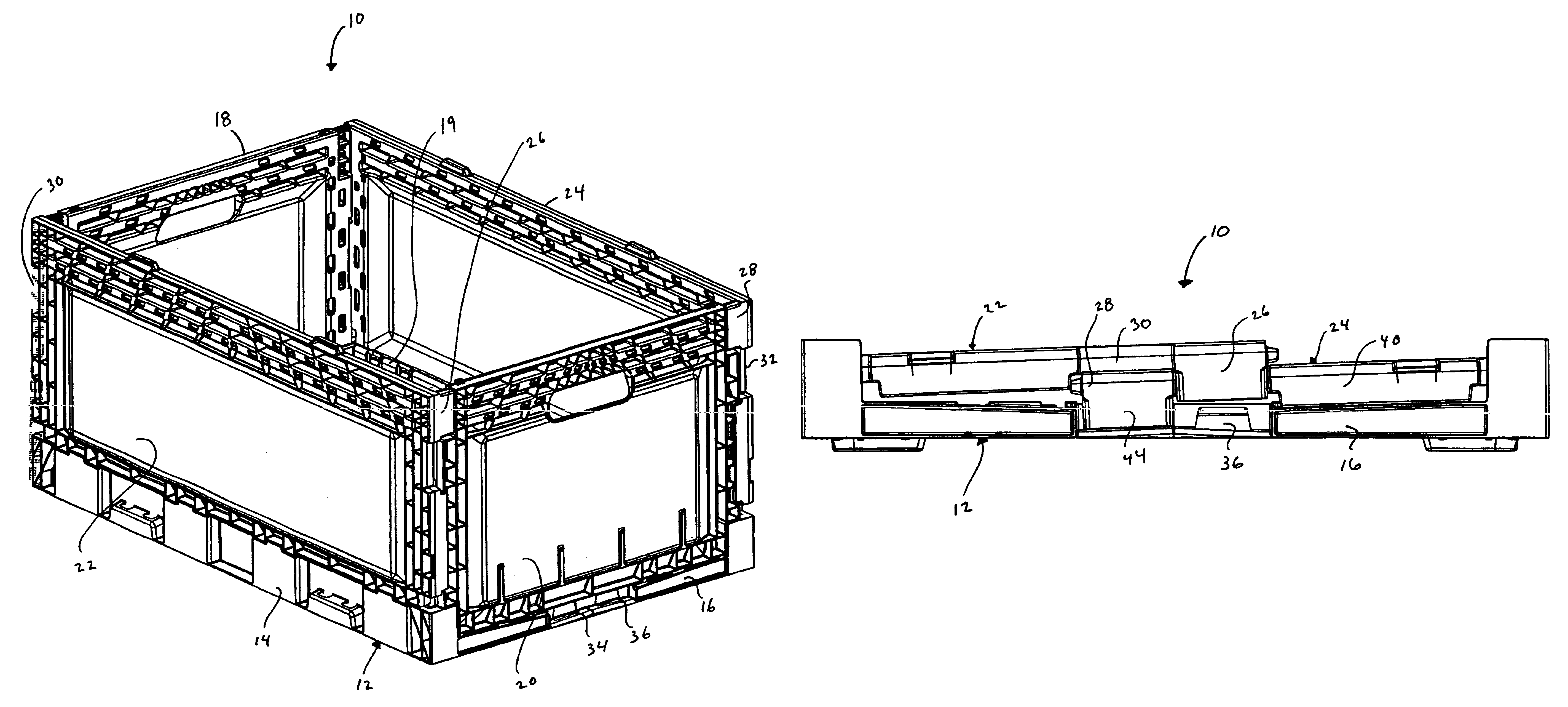
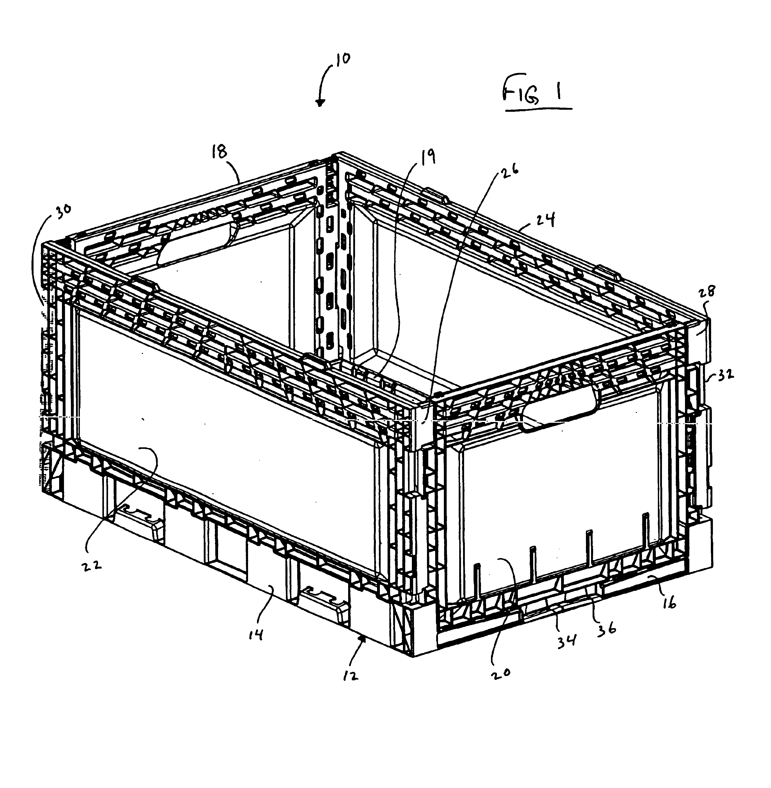
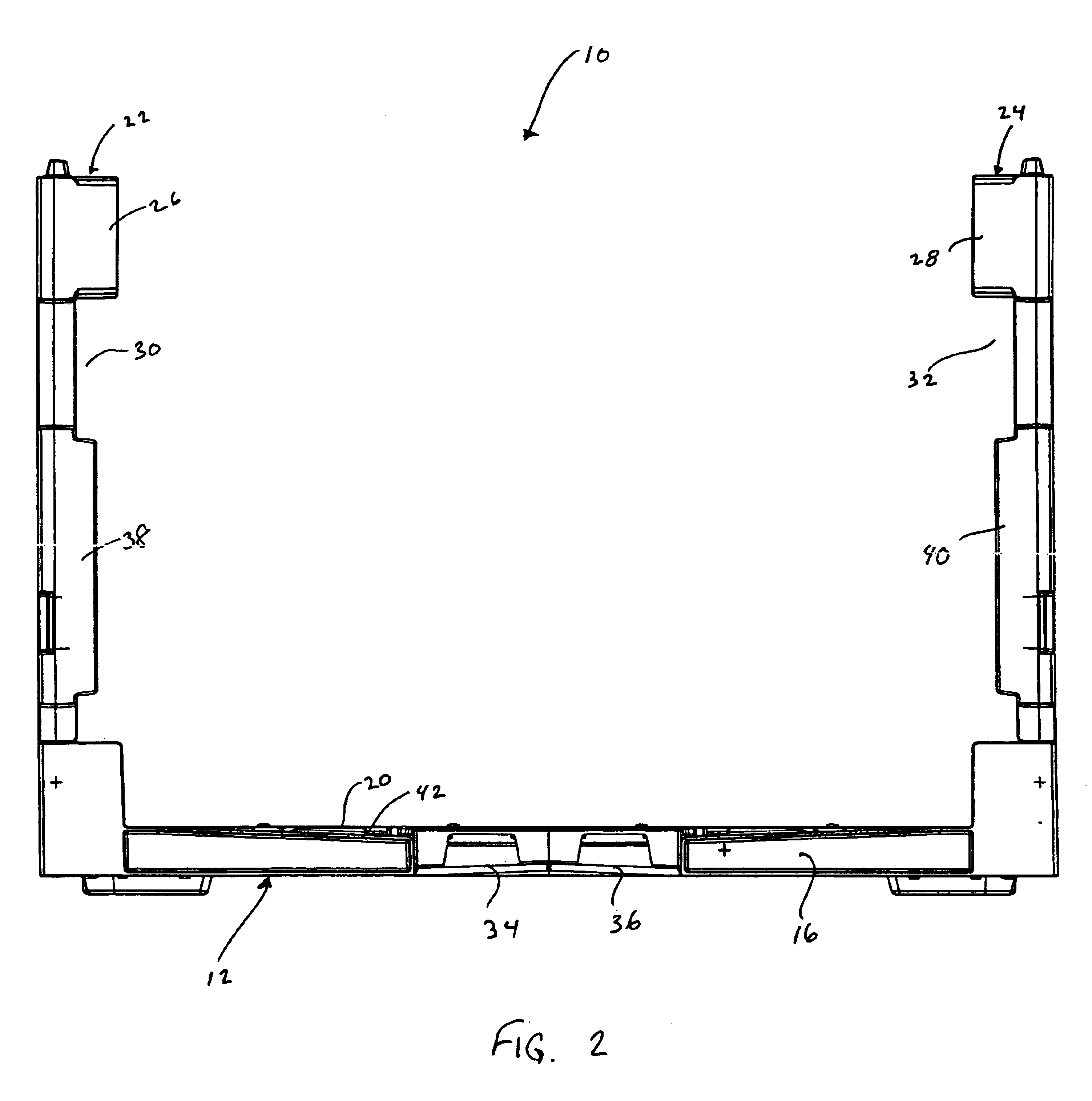
FIGS. 1 through 8 illustrate a collapsible container 10 in accordance with the present invention. Container 10 is rectangular in shape and is generally symmetrical about each center line. The components of container 10 are preferably formed by an injection molding process with a polymeric material such as polypropylene, but of course may be formed by any material and process suitable for the application. Container 10 includes a base 12 having a floor portion 13, a pair of first opposed base portions 14 defining first base edges along the sides of container 10, and a pair of second opposed base portions 16 defining second base edges along the ends of container 10.

Container 10 also includes a first pair of opposed walls, generally referred to as end walls 18, 20, each of which is pivotably connected to a corresponding base end portion 16, preferably by way of hinges representatively shown in FIG. 1 as hinge 19. Also included is a second pair of opposed walls, designated as side walls ...


PUM

PropertyMeasurementUnit
areaaaaaaaaaaa
heightaaaaaaaaaa
volumeaaaaaaaaaa

Abstract

A collapsible container includes a base member having a pair of first base edges, and a pair of second base edges having a recessed base area formed therein. A pair of first opposed walls pivotably attached to the first base edges and orientable between an upright an upright orientation and an inwardly folded orientation. A pair of second opposed walls pivotably attached to the second base edges and orientable between an upright orientation and an overlapping folded orientation. Each of the second opposed walls generally corresponding in height and having a projection member arranged to be received within the recessed area of the second base edges when in the overlapping folded orientation, and each side wall has a recessed wall area arranged to receive the projection member of the second opposed wall folded thereon.

Description

BACKGROUND OF THE INVENTION1. Field of the InventionThis invention relates to a collapsible container having at least one pair of opposed overlapping side walls.2. Background ArtSome collapsible containers have walls which may be inwardly folded in order to stack the containers in an efficient and space-conserving manner when not in use. This efficient means of storage is most easily achieved when the container has walls which do not overlap. However, many collapsible containers have relatively tall walls which when assembled in their upright orientation, provide a large container volume and depth. Accordingly, when folded, at least one of the pairs of opposed walls will overlap. Unfortunately, the overlapping wall typically results in less efficient stacking of the collapsed containers, because the second overlapping wall will be forced to sit high upon the first overlapping wall. Accordingly, the package height and the resulting stacking height of the collapsed unit will be relati...

Claims


Application Information

Patent Timeline
Patent Type & Authority Patents(United States)
IPC IPC(8): B65D6/18B65D19/00B65D19/18
CPCB65D11/1833
Inventor APPS, WILLIAM P.GRUBER, ROBERT V.
Owner REHRIG PACIFIC CO INC
Learn More