
Intraocular lens

a technology of intraocular lens and lens ring, which is applied in the field of intraocular lens, can solve the problems of lens dislocation and tilting, and achieve the effects of stable jointed function, maximal stability and centralization in the ey

Inactive Publication Date: 2005-03-08
SUN RAN +1
View PDF13 Cites 4 Cited by
  • Summary
  • Abstract
  • Description
  • Claims
  • Application Information

AI Technical Summary

Benefits of technology

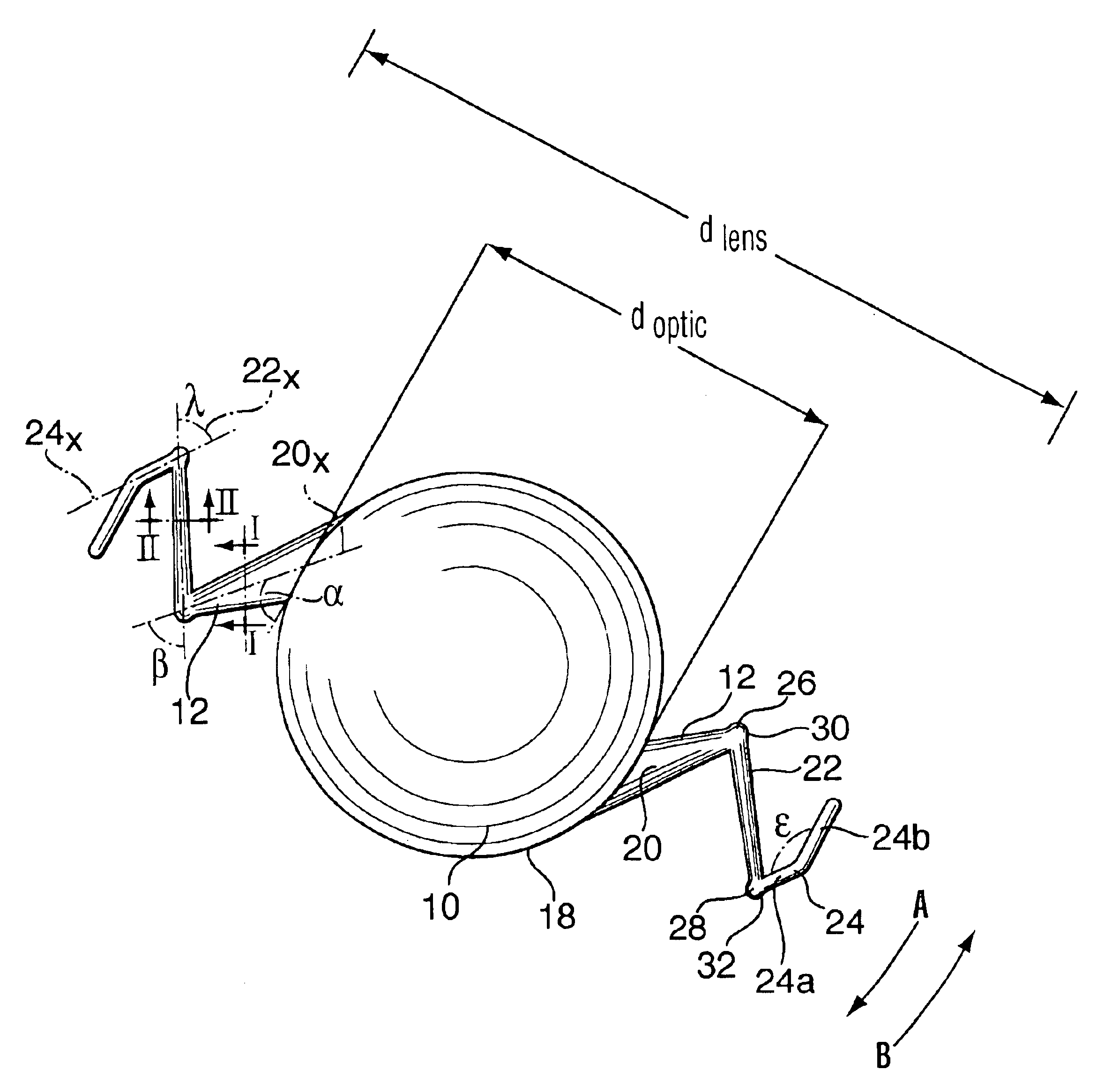
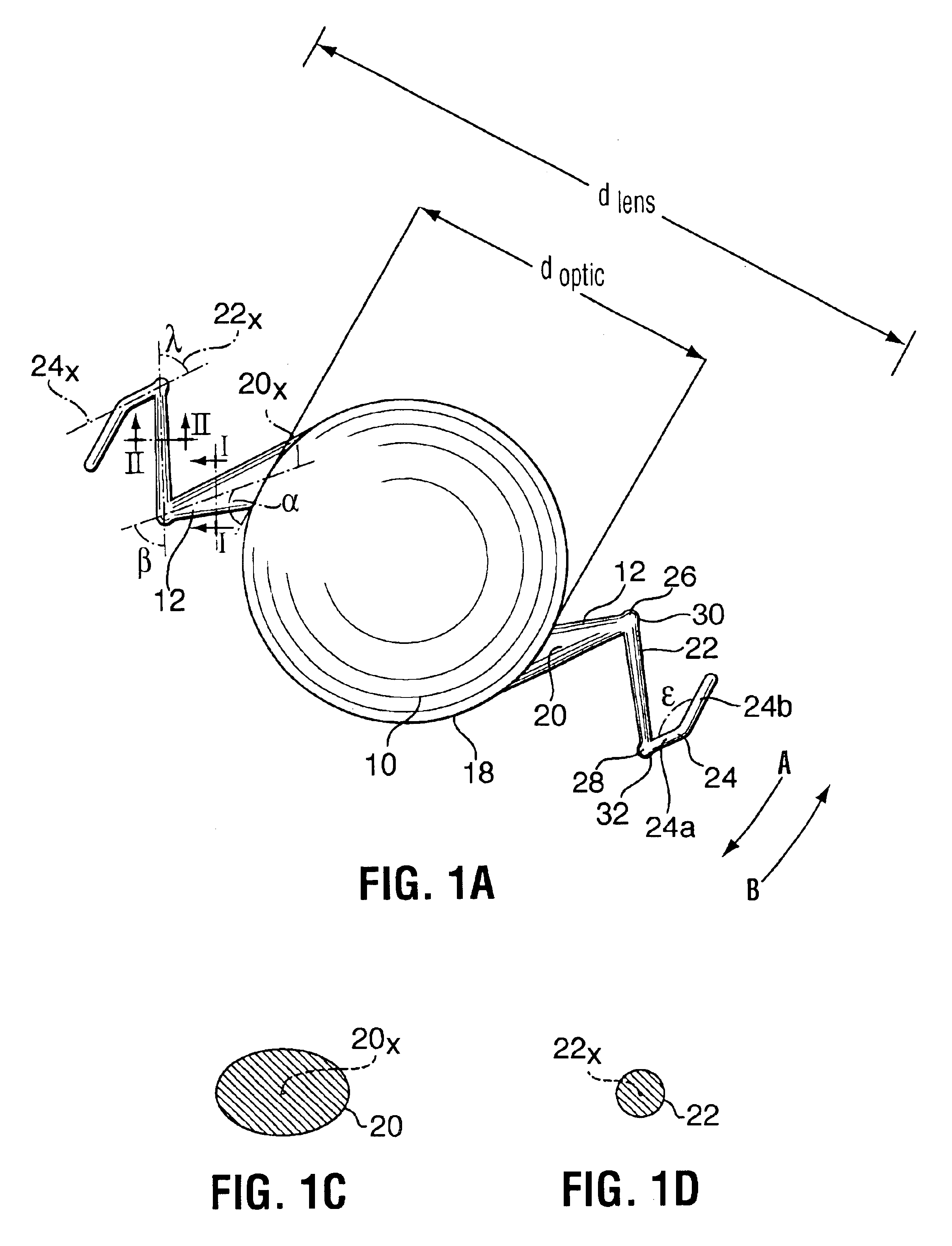
The IOL of this invention utilizes a bionics concept for configuration of the haptic. Thus, the haptic provides a strong and stable jointed function that can provide the IOL with maximal stability and centralization in the eye. Thus, in accordance with one aspect of the invention, there is provided an intraocular lens comprising: an optic; a first haptic and a second haptic connected to the optic and extending outwardly therefrom; each haptic including a base adjacent the optic, a distal foot portion and an intermediate portion connected between the base and the distal foot, the base being connected to the intermediate portion through a first flexible elbow having an angle in a first circumferential direction relative to the to optic and the intermediate portion being connected to the distal foot portion by a second flexible elbow having an angle in a circumferential direction opposite to the first circumferential direction.
The optic can be sized and formed in various ways, as desired, for the various uses of intraocular lens. For example, the lens optic can be enlarged for anterior chamber implantation because larger diameter optics can reduce halo and glare effects over smaller diameter optics. In one embodiment, the optic is formed to reduce postoperative complications, as by forming the edge with sharp corners to reduce migration of epithelial cells and, thereby, to reduce postoperative capsular opacification.
The lens can be made from any clear materials such as polymethylmethacrylate (PMMA) or polypropylene, but is preferably made to be soft, foldable and resilient, for example, formed of silicone, hydrogel or acrylic. The optic can include a photo-chromatic feature, so that it becomes darker when coming in contact with bright light. This feature could eliminate the need to wear sunglasses and, consequently, it may reduce the possibility of retina damage from the sun.

Problems solved by technology

Major fibrosis forces occur after implantation of the IOL and can cause dislocation and tilting of the lens.

Method used


Image

  • Intraocular lens
  • Intraocular lens
  • Intraocular lens

Examples


Embodiment Construction

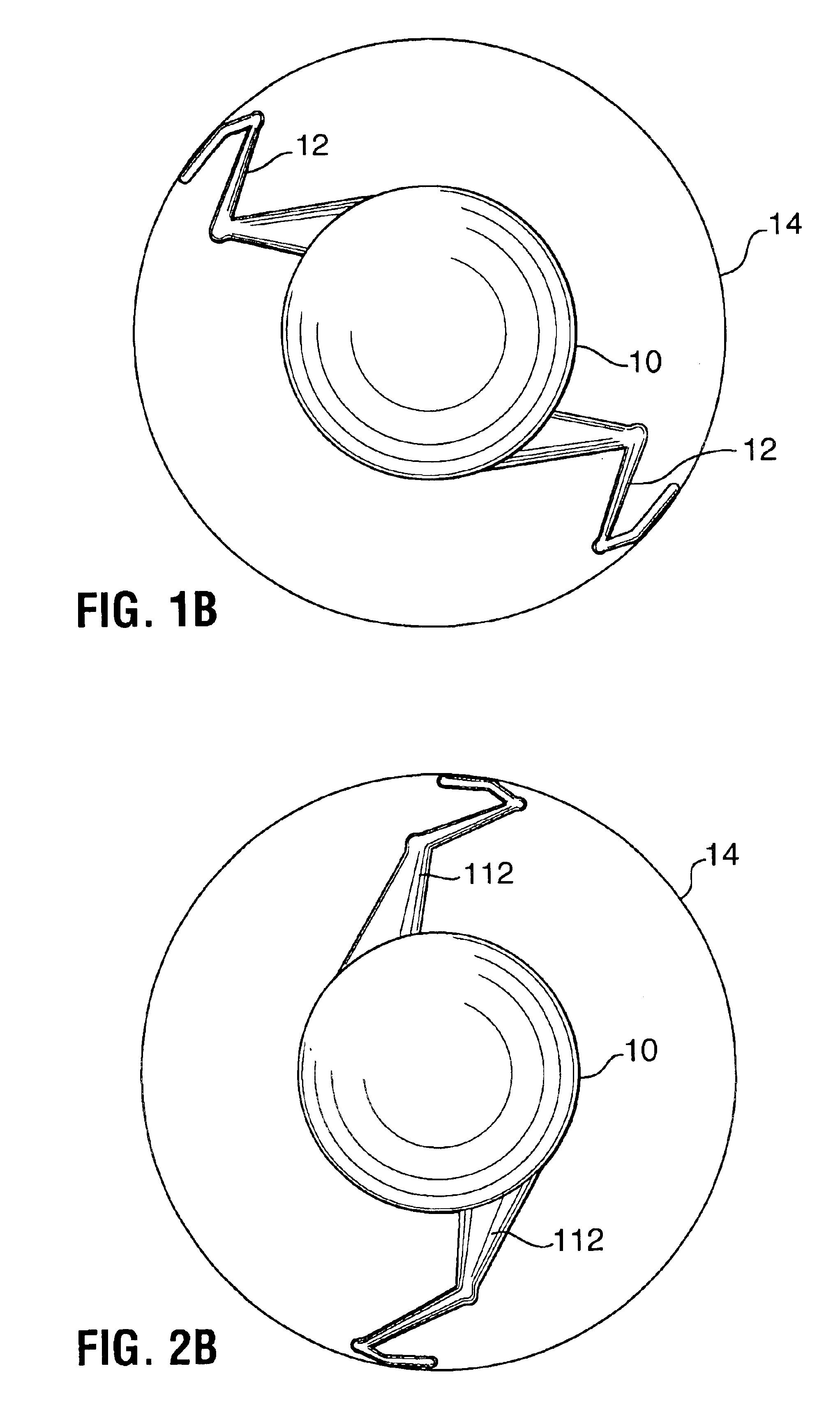
With reference to FIGS. 1A to 1E, an IOL of the present invention includes an optic 10 and two haptics 12 or more extending outwardly from the optic. The IOL is implantable into the capsular bag 14 of the eye wherein the optic acts as the natural lens providing for refractive vision correction and the haptics centralize and stabilize the optic. The haptics and optic, therefore, are sized to provide an effective diameter dlens to extend across the eye capsule for example between 12 and 15 mm. Haptics 12 are positioned relative to the optic and to each other to react forces tending to decentralize and dislodge the IOL. The haptics are therefore, often positioned and configured reverse-symmetrically about the optic. Thus, in this discussion we may describe only one haptic, with it being understood that the other haptic is substantially the reverse mirror image thereof.

Optic 10 and haptics 12 are preferably formed as a one-piece device of foldable, clear material such as silicone, acryl...


PUM


Abstract

An IOL described herein includes an optic and at least a first haptic and a second haptic connected to the optic and extending outwardly therefrom; each haptic is formed with either a frog leg configuration or a running leg configuration, which include a base adjacent the optic, a distal foot portion and an intermediate portion connected between the base and the distal foot, the base being connected to the intermediate portion through a first flexible elbow having an angle in a first circumferential direction relative to the to optic and the intermediate portion being connected to the distal foot portion by a second flexible elbow having an angle in a circumferential direction opposite to the first circumferential direction.

Description

BACKGROUND OF INVENTIONThe present invention relates to an intraocular lens (IOL) for implantation into an eye to correct refractive error.An IOL is a surgical device that can be implanted into the eye to replace cloudy natural lens during cataract surgery or can be implanted into the anterior chamber of the eye to correct refractive errors such as myopia, hyperopia and astigmatism.IOLs have been available for many years for implantation in both anterior and posterior chambers to correct refractive error. The IOL includes an optic held in position in the eye by means of haptics. Previous IOL designs included an optic and two oppositely extending shaped haptics including C-loops or J-loops or a plate-shaped haptic. Optic and haptics can be made as separate pieces attached together or as one-piece of the materials such as polymers including, for example, polymethylmethacrylate (PMMA) or polypropylene or other foldable materials such as silicone, hydrogel or acrylic.Haptic design is cr...

Claims


Application Information

Patent Timeline
IPC IPC(8): A61F2/16
CPCA61F2/1613A61F2002/1681A61F2/16
Inventor SUN, RANLIU, XIU FANG
Owner SUN RAN
Learn More