Channel tuning apparatus

a channel tuning and apparatus technology, applied in the field of channel tuning apparatus, can solve the problems of channel tuning apparatus not being able to tune in the delivered signals, poor operability, and conventional channel tuning apparatus

Inactive Publication Date: 2005-03-08
PANASONIC CORP
View PDF6 Cites 17 Cited by
  • Summary
  • Abstract
  • Description
  • Claims
  • Application Information

AI Technical Summary

Benefits of technology

Thus, the channel tuning apparatus is configured to detect and store channels beginning with the channel selected by the user out of available channels or the first signal-carrying channel found after starting automatic channel tuning, start channel tuning beginning with the Center frequency mode, determine the reference frequency mode by searching a certain effective range in sequence, and perform automatic channel tuning with reference to the reference frequency mode, thereby allowing channel tuning even if the frequency is shifted due to some influence.

Problems solved by technology

However, the conventional channel tuning apparatus described above has a problem of poor operability associated with the complex and troublesome manual operations during automatic channel tuning as described above.
Therefore, if the frequency of the signal delivered by a CATV broadcast exceeds the pull-in range of the desired channel selected by the user, there arises another problem that the conventional channel tuning apparatus cannot tune in the delivered signals.
As described above, the conventional channel tuning apparatus has poor operability during automatic channel tuning.
Also, when selecting an unfamiliar CATV mode, the user may select a wrong mode, resulting in an inability to tune to a channel.
Moreover, a proper channel cannot be tuned in if the frequency of the CATV broadcast signals is shifted from the frequency of the desired channel due to some influence.

Method used


Image

  • Channel tuning apparatus
  • Channel tuning apparatus
  • Channel tuning apparatus

Examples


Embodiment Construction

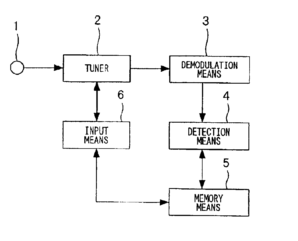
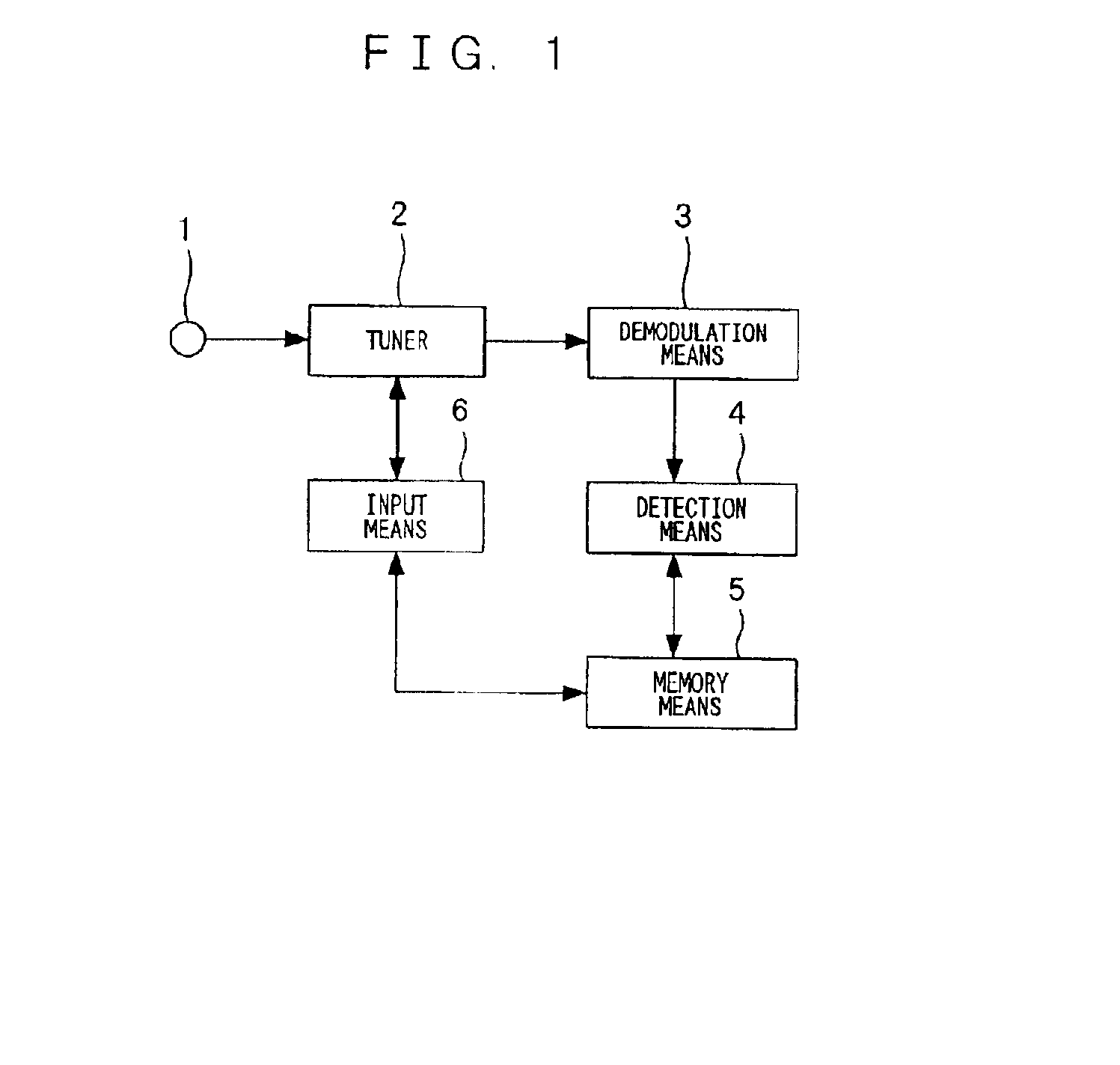
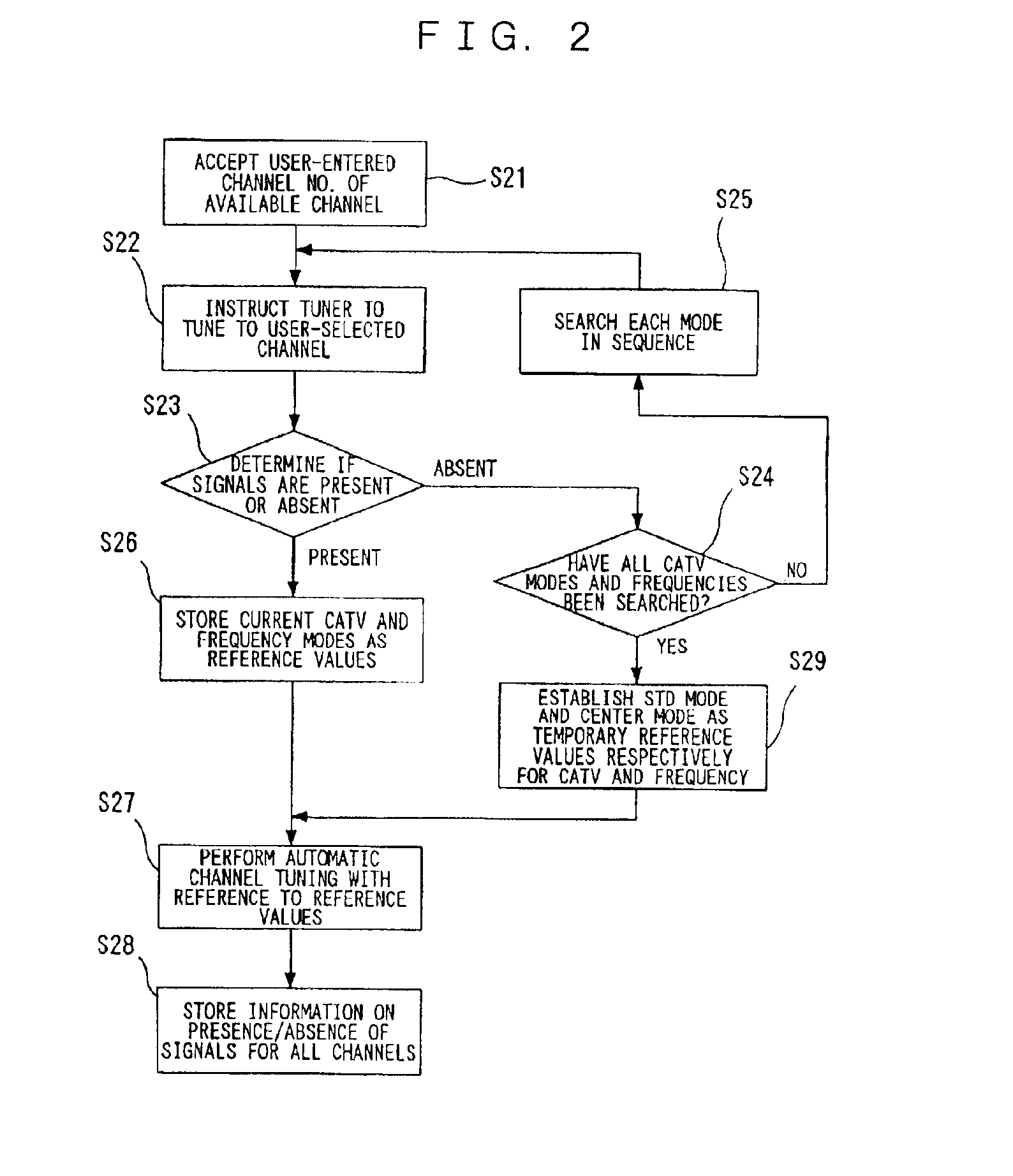
FIG. 1 is a block diagram showing a configuration of a channel tuning apparatus according to an embodiment of the present invention. FIG. 2 is a flowchart showing an operation of CATV mode selection. FIG. 3 is a flowchart showing an operation of automatic channel tuning. FIG. 4 is a diagram illustrating reference mode search patterns. FIG. 5 is a diagram illustrating information about presence or absence of signals on individual channels.

Now, the operation performed after a user selects a CATV mode will be described. Regarding CATV broadcast signals supplied to an antenna, each channel can only be in one broadcast mode out of the STD, HRC, and IRC modes at a time, and different modes never coexist on the same channel. The operation of searching all the channels regardless of the presence or absence of signals and storing signal-carrying channels is referred to as automatic channel tuning.

Before performing automatic channel tuning, it is necessary to set an appropriate CATV broadcast...


PUM


Abstract

A channel tuning apparatus which improves operability by eliminating a need for a user to select a CATV mode and allows reliable channel tuning without misjudging the presence or absence of signals even if a frequency of a CATV broadcast is shifted. The channel tuning apparatus includes a tuner (2) for receiving signals from an antenna (1), a demodulation unit (3) for demodulating the received signals coming from the tuner (2), an input unit (6) for selecting a specific channel for the tuner (2), a detection unit (4) for determining receive mode, and a memory unit (5) for storing the detected data by the detection unit (4), in which the channel tuning apparatus is configured to, before performing automatic channel tuning, tune to a specific channel determined by the input unit (6), detect the receive mode and shift in the received frequency, and store them for use as initial data for automatic channel tuning.

Description

TECHNICAL FIELDThe present invention relates to a channel tuning apparatus for receiving digital television signals, especially signals of CATV broadcasting that has multiple receive modes.BACKGROUND ARTThree broadcasting systems are used for CATV broadcasting in the USA: namely, Standard Cable TV Signals (STD), Harmonic Related Carrier (HRC), and Incremental Related Carrier (IRC) systems.FIG. 6 shows picture carrier frequencies (unit: MHz) of the individual channels (hereinafter “channel” may be abbreviated to “CH”) of the three CATV broadcasting systems. As shown in the figure, all the three CATV broadcasting systems, STD, HRC, and IRC, have different broadcasting frequencies in both CH5 and CH6. For broadcasting on CH5, for example, the STD system uses 79 MHz, HRC system uses 77.75 MHz, and IRC system uses 81 MHz. In this way, the broadcasting frequency varies with the broadcasting system.Since different broadcasting systems use different broadcasting frequencies as described abo...

Claims


Application Information

Patent Timeline
Patent Type & Authority Patents(United States)
IPC IPC(8): H03J1/00H04N5/50H03J5/02H03J7/18H04B1/16H04N5/44H04N7/10
CPCH03J1/0008H03J1/0058H04N21/6118H04N21/4383H04N21/44209H04N5/50H04N7/10
Inventor OHMATSU, TAKAYUKI
Owner PANASONIC CORP
Why Eureka
Try Eureka