
Electronic circuit control element with tap element

a technology of electronic circuit control and tap element, which is applied in the direction of electric variable regulation, process and machine control, instruments, etc., can solve the problems of reducing supply efficiency, requiring a large area, and high price of resistor b>32/b>

Inactive Publication Date: 2005-03-08
POWER INTEGRATIONS INC
View PDF24 Cites 88 Cited by
  • Summary
  • Abstract
  • Description
  • Claims
  • Application Information

AI Technical Summary

Benefits of technology

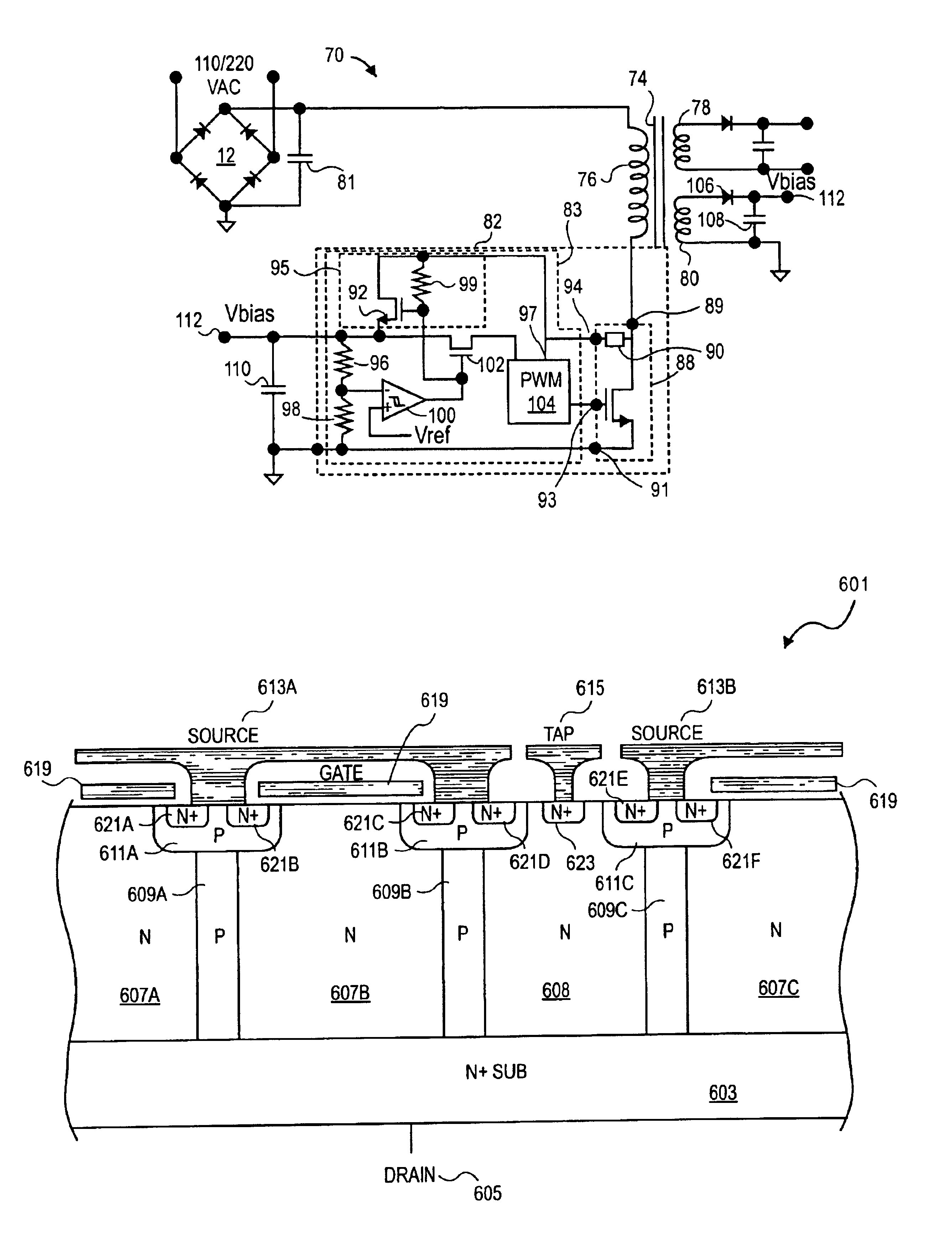
An integrated control element with power transistor and tap element is disclosed. In one embodiment, a control element according to embodiments of the present invention includes a power transistor having first, second, third and fourth terminals. A control circuit is included, which is coupled to the third and fourth terminals of the power transistor. The power transistor adapted to switch a current between the first and second terminals in response a control signal to be received from the control circuit at the third te

Problems solved by technology

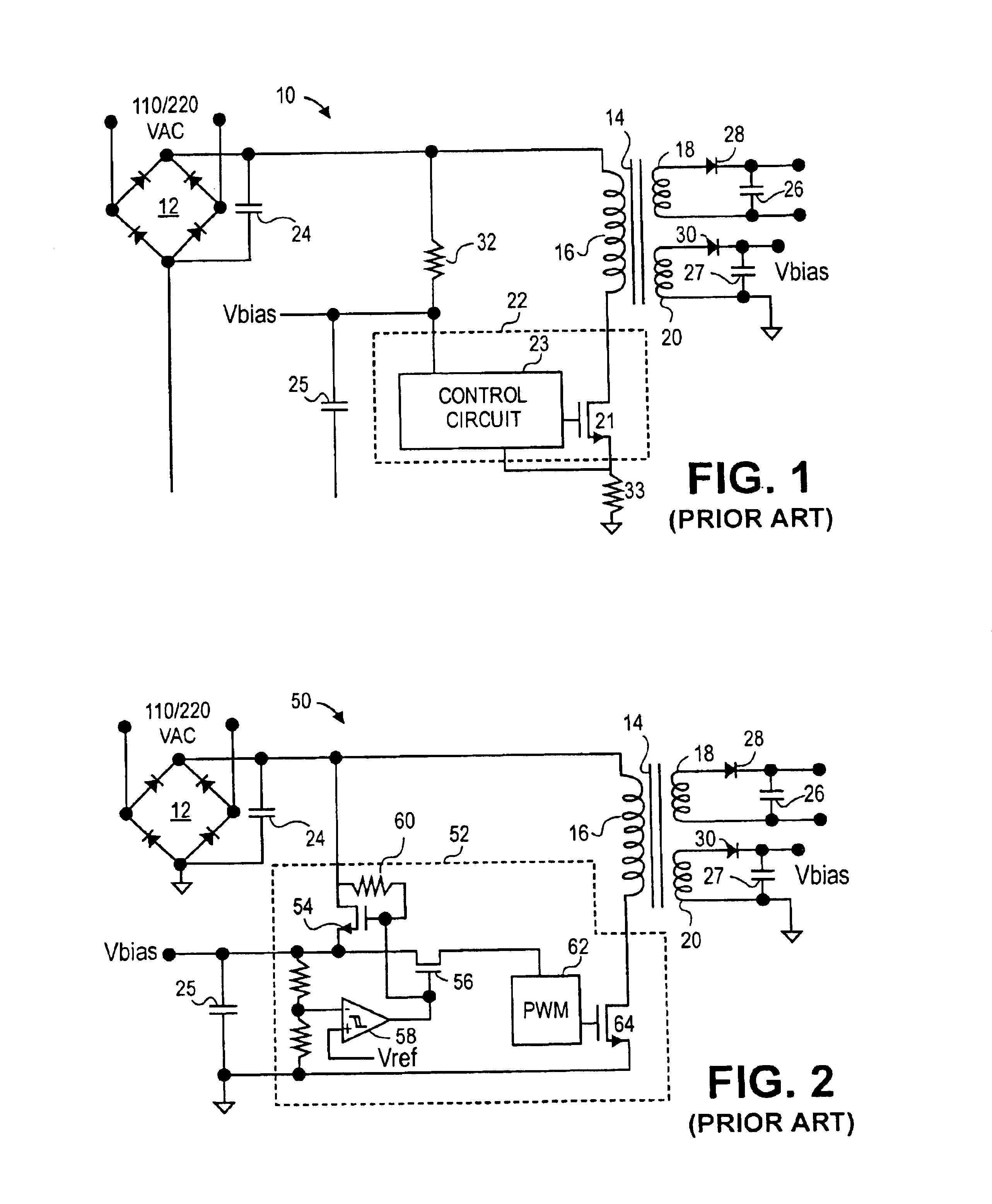
Unfortunately, resistor 32 is expensive, requires a large area in the power supply and lowers supply efficiency by dissipating power continuously, even after the start-up function is completed.
Drawbacks of this approach are the cost, size and power dissipation of resistor 33.
However, the voltage regulator in power supply chip 52 includes a high-voltage offline transistor 54 that consumes a significant area on power supply chip 52 and is also prone to electrical static discharge (ESD) and safe operating area (SOA) damage.
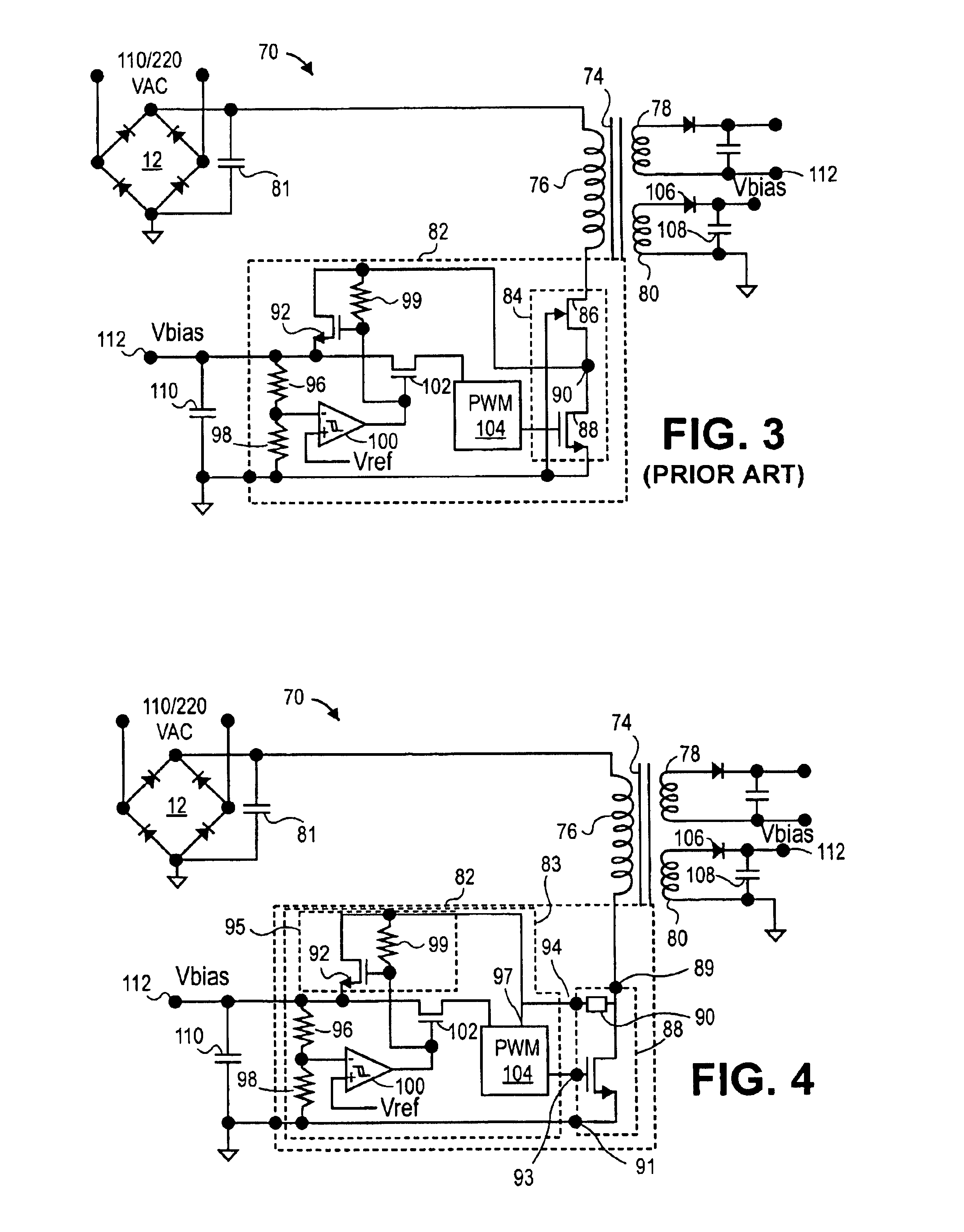
The main limitation of this approach is that the MOSFET 84 used in power supply 70 is limited to one that can be monolithically integrated on the chip 82.
In some cases, discrete power devices with higher efficiency may be available, but cannot be employed in the monolithic approach of power supply 70.

Method used


Image

  • Electronic circuit control element with tap element
  • Electronic circuit control element with tap element
  • Electronic circuit control element with tap element

Examples


Embodiment Construction

A novel control element including a power transistor with a tap element is disclosed. In the following description, numerous specific details are set forth in order to provide a thorough understanding of the present invention. It will be apparent, however, to one having ordinary skill in the art that the specific detail need not be employed to practice the present invention. In other instances, well-known materials or methods have not been described in detail in order to avoid obscuring the present invention.

The following description uses the example of a power supply to illustrate the benefits of the present invention. It will be apparent to one skilled in the art that the techniques are not limited to use in power supplies but apply to any electronic circuit employing a control element with integrated power transistor.

In general, a power supply according to embodiments of the present invention includes a power control element that includes a control circuit and a power transistor....


PUM


Abstract

A technique for controlling a power supply with power supply control element with a tap element. In one embodiment, a power supply regulator includes a power transistor having first, second, third and fourth terminals. A control circuit is included, which is coupled to the third and fourth terminals of the power transistor. The power transistor is configured to switch a current between the first and second terminals in response a control signal received from the control circuit at the third terminal. A voltage between the fourth and second terminals of the power transistor is substantially proportional to a current flowing between the first and second terminals when a voltage between the first and second terminals is less than a pinch off voltage. The voltage between the fourth and second terminals of the power transistor is substantially constant and less than the voltage between the first and second terminals when the voltage between the first and second terminals is greater than the pinch off voltage.

Description

BACKGROUND OF THE INVENTION1. Field of the InventionThe present invention relates generally to control elements used in electronic circuits and, more specifically, the present invention relates to control elements with integrated power transistors.2. Background InformationTwo of the primary goals in the design of control elements with integrated power transistors are cost and performance. Cost is generally reduced when the number of external components required in the electronic circuit are reduced, and when smaller, more efficient power transistors are employed. Performance may be improved by adopting a more efficient power transistor, which increases efficiency, and by lowering the manufacturing variance, which allows better control of critical parameters such as the peak current delivered by the power transistor.FIG. 1 shows a power supply 10, which is provided as an example of an electronic circuit using a control element with power transistor. The control element 22 for this kn...

Claims


Application Information

Patent Timeline
IPC IPC(8): G05F1/10G05F1/14H01L29/66H01L29/02H01L29/78H01L29/06H01L29/08H01L29/423H01L29/40H02M3/28H02M3/335
CPCG05F1/14H02M3/33553H01L29/0653H01L29/407H01L29/7802H01L29/7813H02M1/36H02M3/335H02M3/33507H02M3/33561H01L29/7803H01L29/0634H01L29/0847H01L29/42368H02M2001/0009H02M1/0009
Inventor DISNEY, DONALD R.
Owner POWER INTEGRATIONS INC
Learn More