
System and method of controlling the start-up of an adjustable speed motor drive based sinusoidal output power conditioner

a technology of adjustable speed and sinusoidal output, applied in the field of power conditioning, can solve the problems of transformer saturation, current power conditioners often trip, load to trip, etc., and achieve the effect of reducing the difference between load voltage and voltag

Inactive Publication Date: 2008-12-23
EATON CORP
View PDF37 Cites 37 Cited by
  • Summary
  • Abstract
  • Description
  • Claims
  • Application Information

AI Technical Summary

Benefits of technology

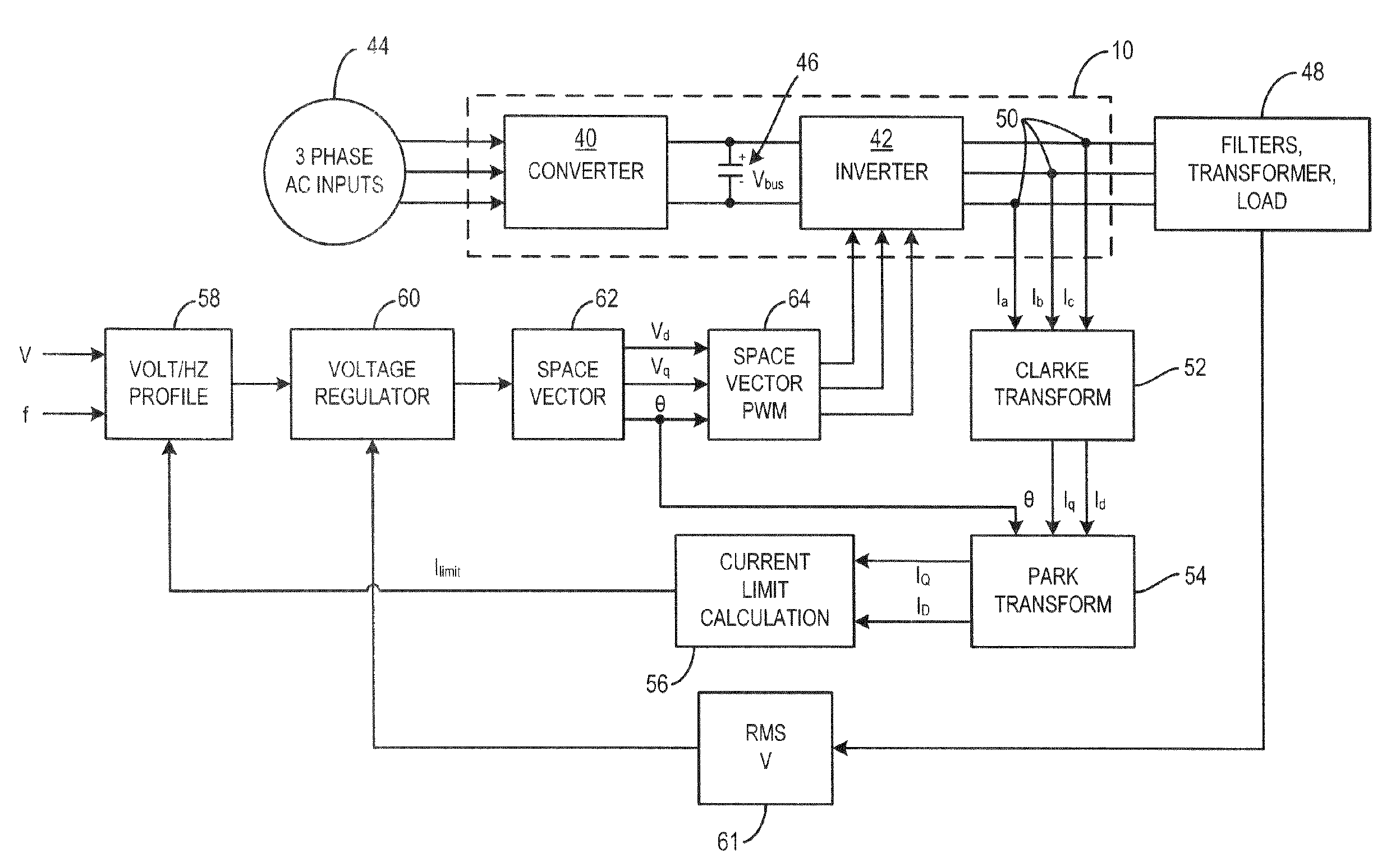
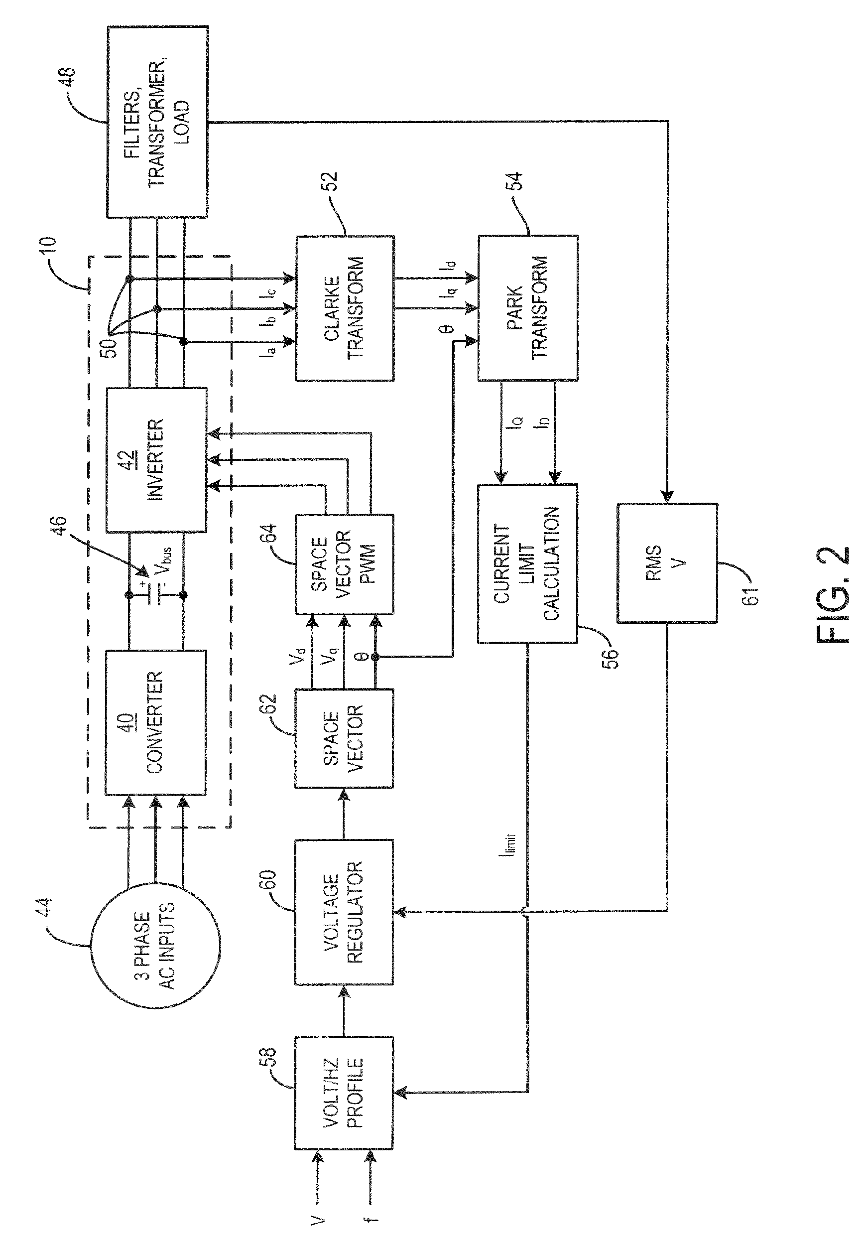
The present invention provides a system and method for controlling a power conditioner connected to a load. The system includes a motor drive with a current feedback circuit that monitors current being fed to a transformer connected between the motor drive and the load. The controller adjusts the V / Hz profile along which the motor drive operates to prevent transformer saturation during start-up. The power conditioner includes a DC bus, an inverter connected to the DC bus, and a transformer connected to the inverter. The controller regulates the inverter to prevent current saturation of the transformer during transition of the power conditioner from an initial state to steady-state. The method includes initially providing power to the load according to a default V / Hz profile and monitoring output current of the inverter. The inverter provides power according to a new V / Hz profile if the output current exceeds a current limit. The technical effects of the invention include preventing transformer saturation, reducing load voltage deviation, and improving power conditioning efficiency.

Problems solved by technology

However, current power conditioners often trip, or cause the load to trip, when strict voltage and current constraints are not met.
At start-up of the power conditioner, it is not uncommon for the transformer to become saturated and, thus, fail as a result of SCR failure or control problems.
This saturation can cause damage to the transformer.
If this condition is maintained, the transformer will fail.
In any event, undesirable system failure occurs.
Saturation of the transformer can be particularly problematic during start-up of the power conditioner.
As described above, this DC bias can cause transformer saturation and, ultimately, component or system failure.

Method used


Image

  • System and method of controlling the start-up of an adjustable speed motor drive based sinusoidal output power conditioner
  • System and method of controlling the start-up of an adjustable speed motor drive based sinusoidal output power conditioner
  • System and method of controlling the start-up of an adjustable speed motor drive based sinusoidal output power conditioner

Examples


Embodiment Construction

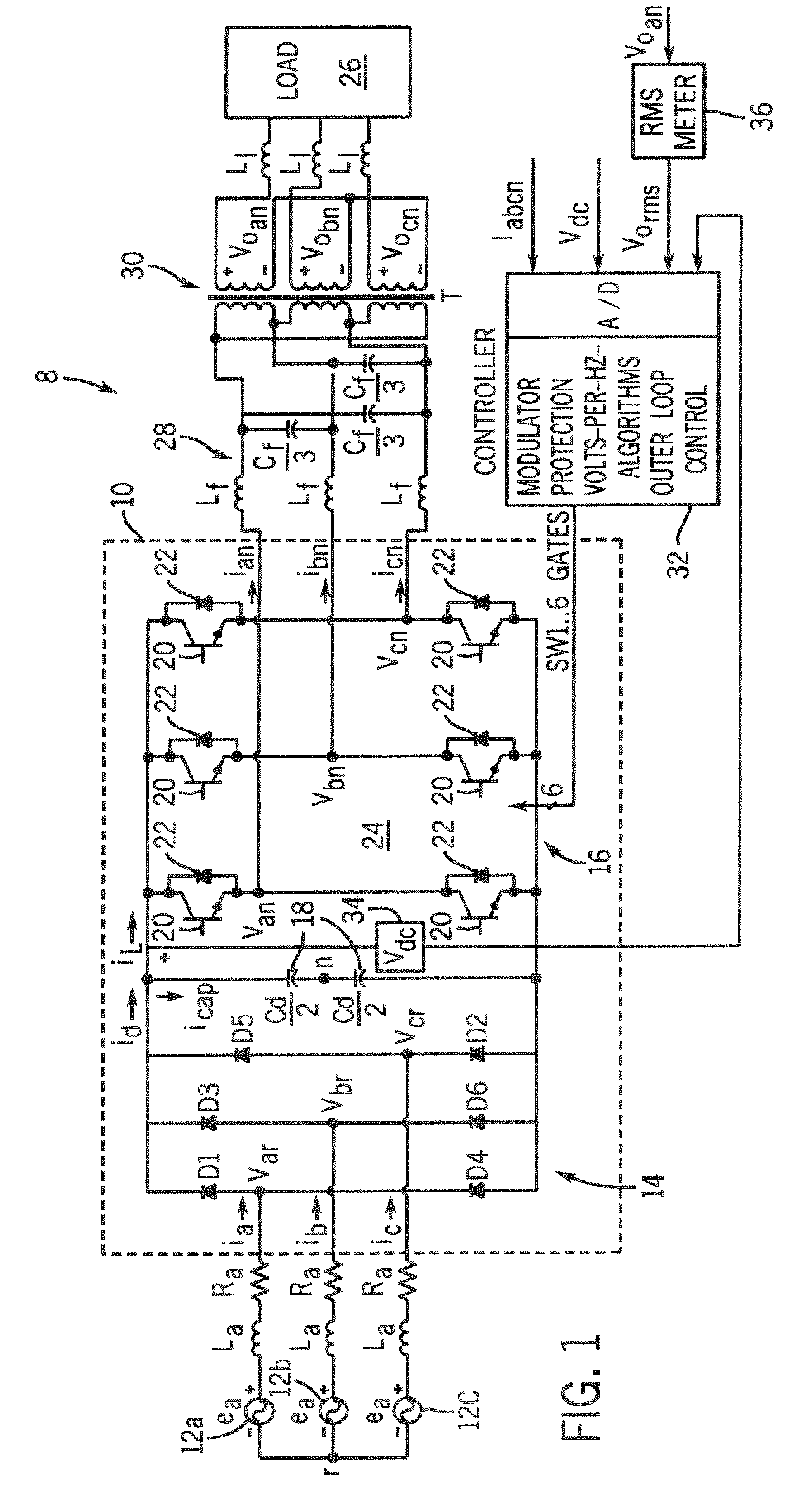
[0028]Referring now to FIG. 1, a power conditioner 8 having an adjustable speed motor drive 10 is shown. The adjustable speed drive (ASD) is designed to receive a three AC power input, rectify the AC input, and perform a DC / AC conversion of the rectified segment into a three-phase alternating voltage of variable frequency and amplitude that is supplied to a load. In a preferred embodiment, the ASD operates according to an exemplary V / Hz characteristic. The motor drive provides voltage regulation of ±1% in steady state with less than 3% total harmonic distortion, ±0.1 Hz in output frequency, and fast dynamic step load response over a full load range. It is contemplated that the motor drive is to be used as a fixed frequency / fixed voltage sinusoidal voltage conditioner and, as such, may be connected to a motor load, a non-motor load, a linear load, a non-linear load, motors operating at line frequency and voltage, a transformer coupled load, and the like. Hereinafter, for purposes of ...


PUM


Abstract

A motor drive for conditioning power to be delivered to a load includes a current feedback circuit that monitors current being fed to a transformer connected between the motor drive and the load. Based on the total current input to the transformer, a controller adjusts the V / Hz profile along which the motor drive operates. In this regard, the motor drive operates according to a V / Hz profile during start-up that prevents transformer saturation.

Description

BACKGROUND OF THE INVENTION[0001]The present invention relates generally to power conditioning and, more particularly, to a system and method of controlling a motor drive.[0002]Motor drives are frequently used in industrial applications to condition power and otherwise control electric driven motors such as those found with pumps, fans, compressors, cranes, paper mills, steel mills, rolling mills, elevators, machine tools, and the like. Motor drives typically provide a volts-per-hertz control and have greatly improved the efficiency and productivity of electric driven motors and applications. Increasingly, motor drives are taking the form of adjustable-speed drives (ASD) that are adept at providing variable speed and / or variable torque control to an electric driven motor. Heretofore, motor drives have been used solely to control or otherwise condition power to a motor load.[0003]Power to non-motor loads is usually controlled through a power conditioner that is specifically designed ...

Claims


Application Information

Patent Timeline
Patent Type & Authority Patents(United States)
IPC IPC(8): H02P27/04
CPCH02P1/04H02P27/047
Inventor LEE, KEVINAHLGREN, JYRKI K.WALLACE, IAN T.DORING, THOMAS M.
Owner EATON CORP
Learn More