Optically-based location system and method for determining a location at a structure

Inactive Publication Date: 2005-03-08
GOOGLE TECH HLDG LLC
View PDF16 Cites 131 Cited by
  • Summary
  • Abstract
  • Description
  • Claims
  • Application Information

AI Technical Summary

Problems solved by technology

The smaller-scale location technologies present many more unsolved problems than the large-scale E-911 technology.
One of the most challenging feats resides in the creation of technology that is able to locate a device within or around structures.
Equipment that uses radio frequency (“RF”) signals to capture Receive Signal Strength (“RSS”), Time Difference of Arrival (“TDoA”), or Angle of Arrival (“AoA”) clues have limited location accuracy and often require an expensive supporting infrastructure.
The realities of the indoor environment prevent RF schemes from bei

Method used


Image

  • Optically-based location system and method for determining a location at a structure
  • Optically-based location system and method for determining a location at a structure
  • Optically-based location system and method for determining a location at a structure

Examples


Embodiment Construction

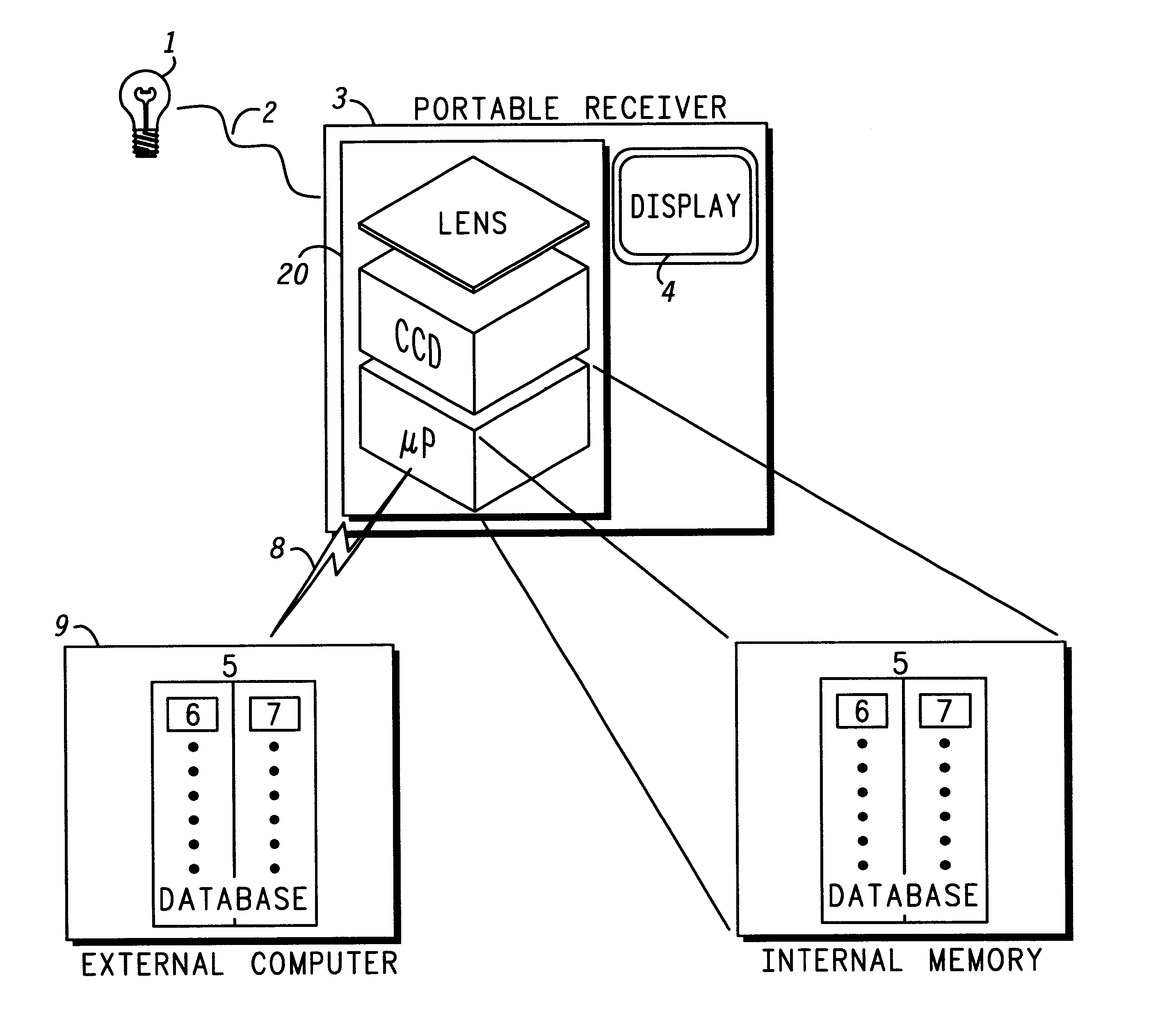
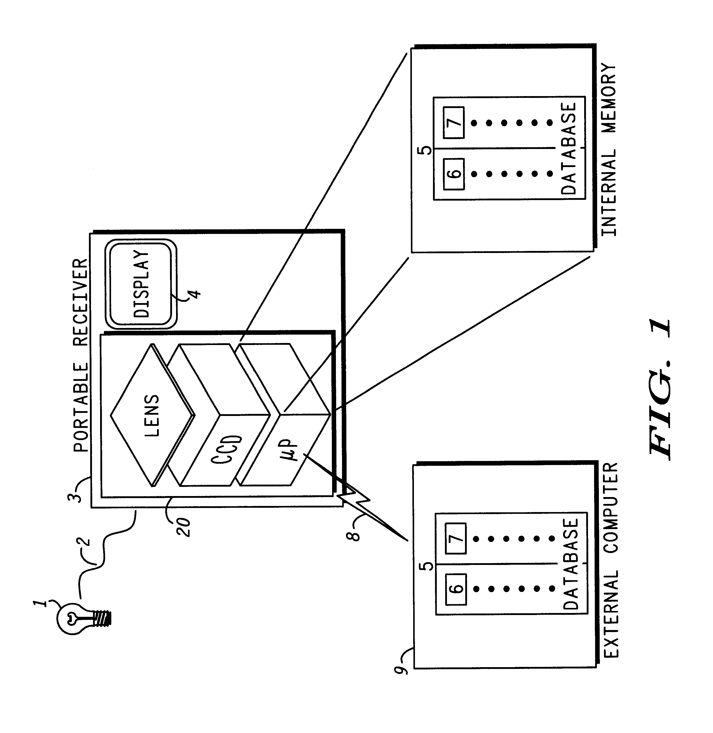
It is often forgotten that indoor environments were constructed to minimize audio and optical interference. Walls were erected and doors were installed to keep in-building conversations private and to substantially prevent light from dispersing from one area to another. A typical building, for example, is configured such that room A has one light source and room B has another light source. Thus, the light emitting from each respective source (e.g., the transmitted signal) cannot interfere with light emitting from another source. On the other hand, if RF sources (transmitters) are used, multiple signals originating from one area can and do interfere with each other and also with signals originating from other areas, including areas behind walls. When RF sources are used with in-building location detection systems, the interference skews a location sought to be estimated.

Instead of applying RF signals for determining location, the present invention uses optical signal technology in a ...


PUM


Abstract

An optically based location system and method of determining a location at a structure include a lighting infrastructure having lights at a structure. Each light is configured to illuminate and to transmit a respective relative or absolute terrestrial position through modulation of emitted light. An optical receiver is configured to detect the lights, to demodulate the position of detected lights, and to determine from the detection a position of the receiver. The receiver can have a conventional optical detector for determining a two-dimensional position of the receiver relative to a detected light, or can have a three-dimensional spot collimating lens and charged couple device optical detector for determining a three-dimensional position of the receiver relative to a detected light. The receiver and lights can be synchronized for converting a delay time into a distance measurement to calculate a distance between a light and the receiver.

Description

BACKGROUND OF THE INVENTION1. Field of the InventionThe invention lies in the field of electronic location determination. The invention relates to an optically based location system and a method for determining a location at a structure.2. Description of the Related ArtIn the recent past, the Federal Communications Commission (FCC) has promulgated standards related to the Emergency-911 (“E-911”) initiative. This initiative has set the initial standards for a communications system that, in the future, will precisely locate a particular person or object. Particularly, the initiative relates to precisely determining the location of a particular cellular telephone. As a result, location technologies have been developing rapidly. The rush to complete E-911, in particular, has compelled many cellular system designers to develop a scheme that will satisfy the location requirements set by the FCC.Simultaneously, smaller-scale location opportunities, such as personal security and asset-manag...

Claims


Application Information

Patent Timeline
IPC IPC(8): G01S1/00G01S1/70G01S5/16G01S3/78G01S3/781G01S5/00H04B10/10
CPCG01S1/70H04B10/11G01S5/16G01S3/781G01S2201/01G01S1/7038G01S1/7034
Inventor PERKINS, MATTHEW R.LIN, TZER-HSOPATWARI, NEAL K.O'DEA, ROBERT J.
Owner GOOGLE TECH HLDG LLC
Why Eureka
Try Eureka