
Locking apparatus

a technology of locking apparatus and door frame, which is applied in the direction of mechanical control devices, keyhole guards, instruments, etc., can solve the problems of time and labor, many parts involved, etc., and achieve the effect of convenient installation on the door

Inactive Publication Date: 2005-03-15
UNIREC +1
View PDF9 Cites 52 Cited by
  • Summary
  • Abstract
  • Description
  • Claims
  • Application Information

AI Technical Summary

Benefits of technology

"The present invention provides a locking apparatus for doors that involves a small number of parts, is easy to install, and can lock and unlock a door even if the key is lost. The locking apparatus includes a lock driver, a biometric verifier, a detector, an alarm, an alarm power supply circuit, a detector switch, an alarm switch, and a normally-closed disconnecting switch. The lock driver can electrically lock and unlock the door, while the key can be used to mechanically operate the lock driver. The detector can detect manipulation on the key cylinder and the alarm can be activated if a manipulation is detected. The locking apparatus can be easily installed on a door and is effective in preventing unauthorized unlocking."

Problems solved by technology

The related art has another problem that it involves many parts and needs time and labor to install it on the door 103 because it employs the two separate lock mechanisms, i.e., the electronic lock 101 and cylinder lock 102.

Method used


Image

  • Locking apparatus
  • Locking apparatus
  • Locking apparatus

Examples


first embodiment

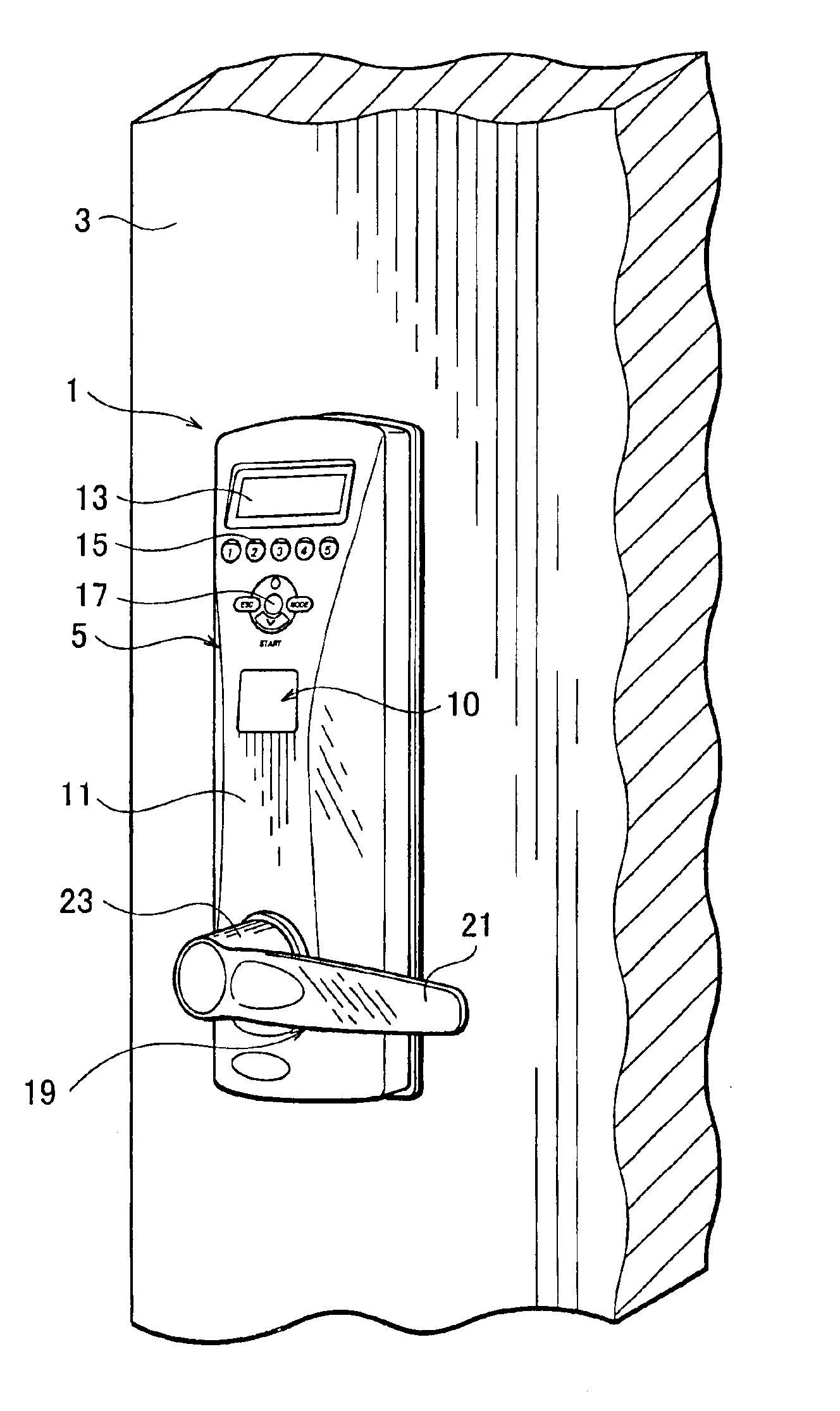
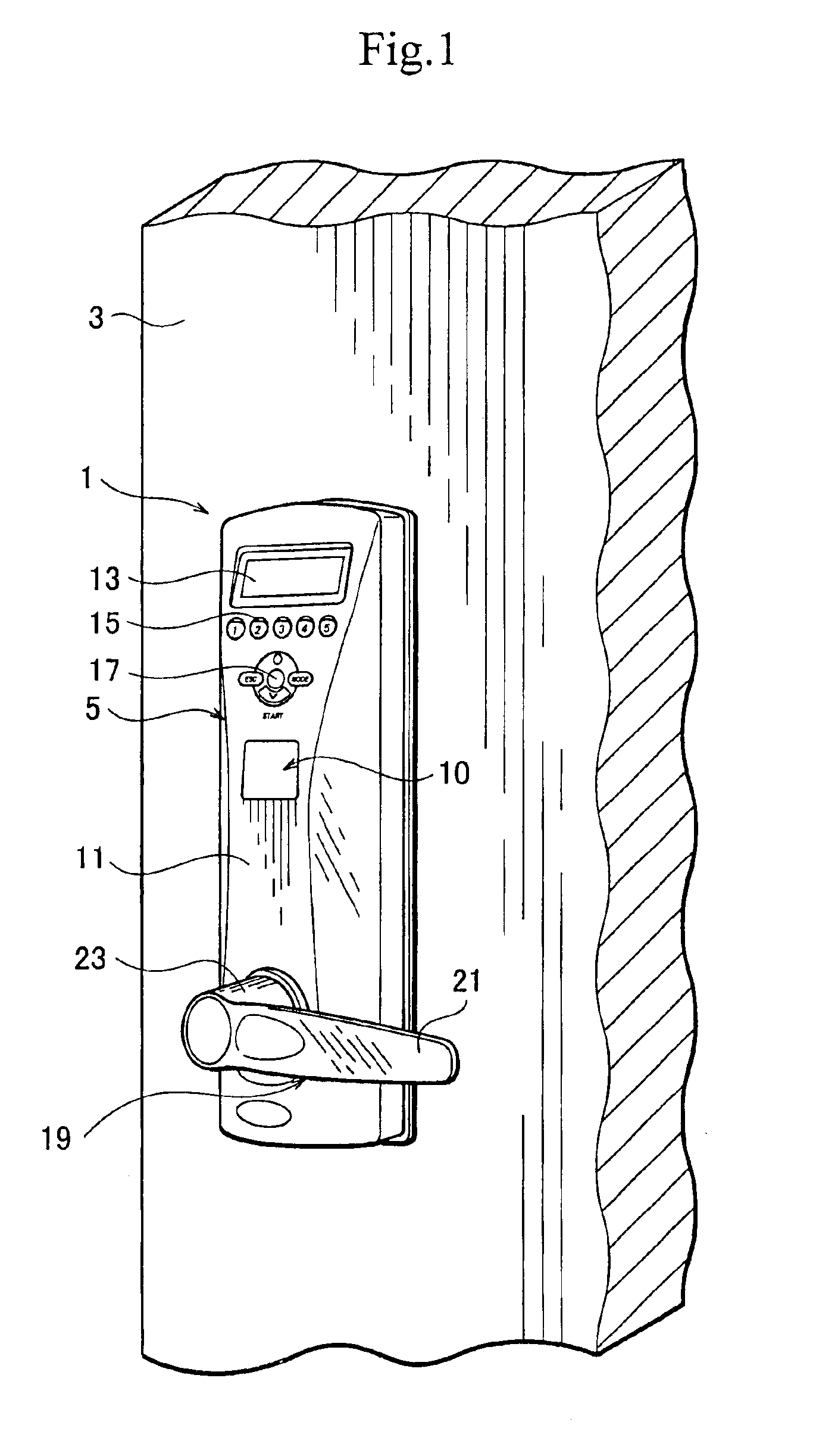
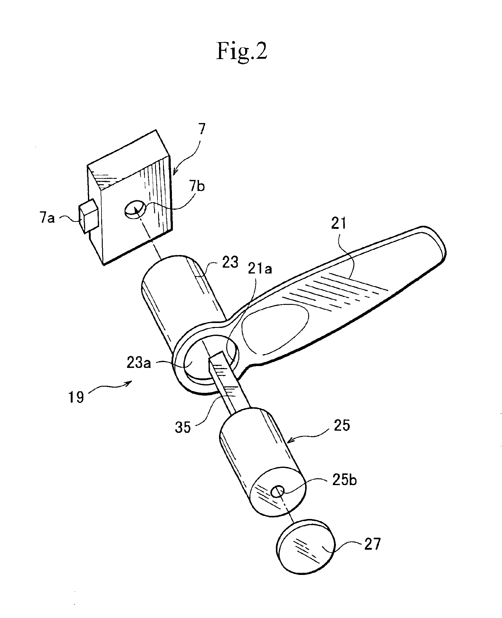
FIG. 1 is a perspective view partly showing a door with a locking apparatus according to the first embodiment of the present invention, FIG. 2 is an exploded view showing the locking apparatus of FIG. 1, and FIGS. 3A and 3B are sectional views showing a fingerprint verifier of the locking apparatus of FIG. 1 before and after inserting a finger into the verifier.

The locking apparatus 1 according to the first embodiment allows a user to optionally choose a usual locking / unlocking operation using a key or an easy locking / unlocking operation using no key. The locking apparatus 1 has an exterior unit 5 attached to the exterior side of a door 3. Inside the door 3, the locking apparatus 1 has a lock driver 7 to lock and unlock the door 3. The locking apparatus 1 also has a fingerprint read / verify unit 9 forming a part of a biometric verifier 10. When a person wants to lock or unlock the door 3, the person puts a finger on the read / verify unit 9. Then, the read / verify unit 9 reads biometric...

second embodiment

FIG. 6 is a circuit diagram showing a locking apparatus according to a second embodiment of the present invention, and FIG. 7 is a sectional view partly showing a key cylinder of the locking apparatus of FIG. 6. The second embodiment of FIGS. 6 and 7 is based on the first embodiment of FIGS. 1 to 5, and therefore, like parts are represented with like reference marks throughout the drawings, and the explanation of like parts will not be repeated.

The second embodiment employs a buzzer or an alarm 34 to give an alarm when the key 31 or a foreign object is inserted into the opening 25b of the key cylinder 25 to manually operate the lock driver 7. In FIG. 6, the second embodiment connects an alarm power supply circuit or a buzzer power supply circuit to the fingerprint read / verify unit 9 that is also connected to the power supply circuit of FIG. 4 of the first embodiment.

The buzzer power supply circuit includes the buzzer 34, a detector switch 36, an auxiliary battery 38 serving as a buz...


PUM


Abstract

A locking apparatus has a lock driver to electrically lock and unlock a door, a fingerprint read / verify unit to receive a fingerprint from a user, verify the received fingerprint by comparing it with registered fingerprint data) and if the fingerprint verification authenticates the user, enable the lock driver to electrically operate, a key cylinder attached to the door, an interlink linking the key cylinder with the lock driver, and a key to manually operate the lock driver in cooperation with the key cylinder and the interlink.

Description

BACKGROUND OF THE INVENTION1. Field of the InventionThe present invention relates to a locking apparatus capable of locking and unlocking a door with a mechanical operation using a key and an electrical operation using biometric information such as a fingerprint.2. Description of Related ArtAn example of a locking apparatus is disclosed in Japanese Unexamined Patent Application Publication No. 2002-70382. FIG. 8 is a front view partly showing the exterior side of a door 103 on which the locking apparatus of the disclosure is installed.The locking apparatus includes an electronic lock 101 and a cylinder lock 102. The locks 101 and 102 are independent of each other and separately lock and unlock the door 103. The lock 101 has a housing 105 fixed to the door 103. The housing 105 has a chamber 109 that is opened and closed with a lid 107 and contains a fingerprint reader. The lock 101 receives electric power from a battery or a DC source.A person who wants to open the door 103 opens the...

Claims


Application Information

Patent Timeline
Patent Type & Authority Patents(United States)
IPC IPC(8): G07C9/00E05B35/08E05B49/00E05B45/10
CPCG07C9/00563Y10T70/7068Y10T70/5832E05B49/00
Inventor YAMAGISHI, JUNICHI
Owner UNIREC
Learn More