This helps you quickly interpret patents by identifying the three key elements:
Problems solved by technology
Method used
Benefits of technology
The invention provides a method of inflating a tire, or vehicle tire, that minimizes the amount of time needed for same. The method of inflating a tire with a tire pressure management system includes introducing continuous fluid flow of a fluid into the tire
Problems solved by technology
Over time, the energy costs for operating a tire inflation management system can grow.
Also, although not continuous, tire inflation management systems chronically draw com
Method used
Image
Click on the blue label to locate the original text in one second.
Reading with bidirectional positioning of images and text.
Examples
Example
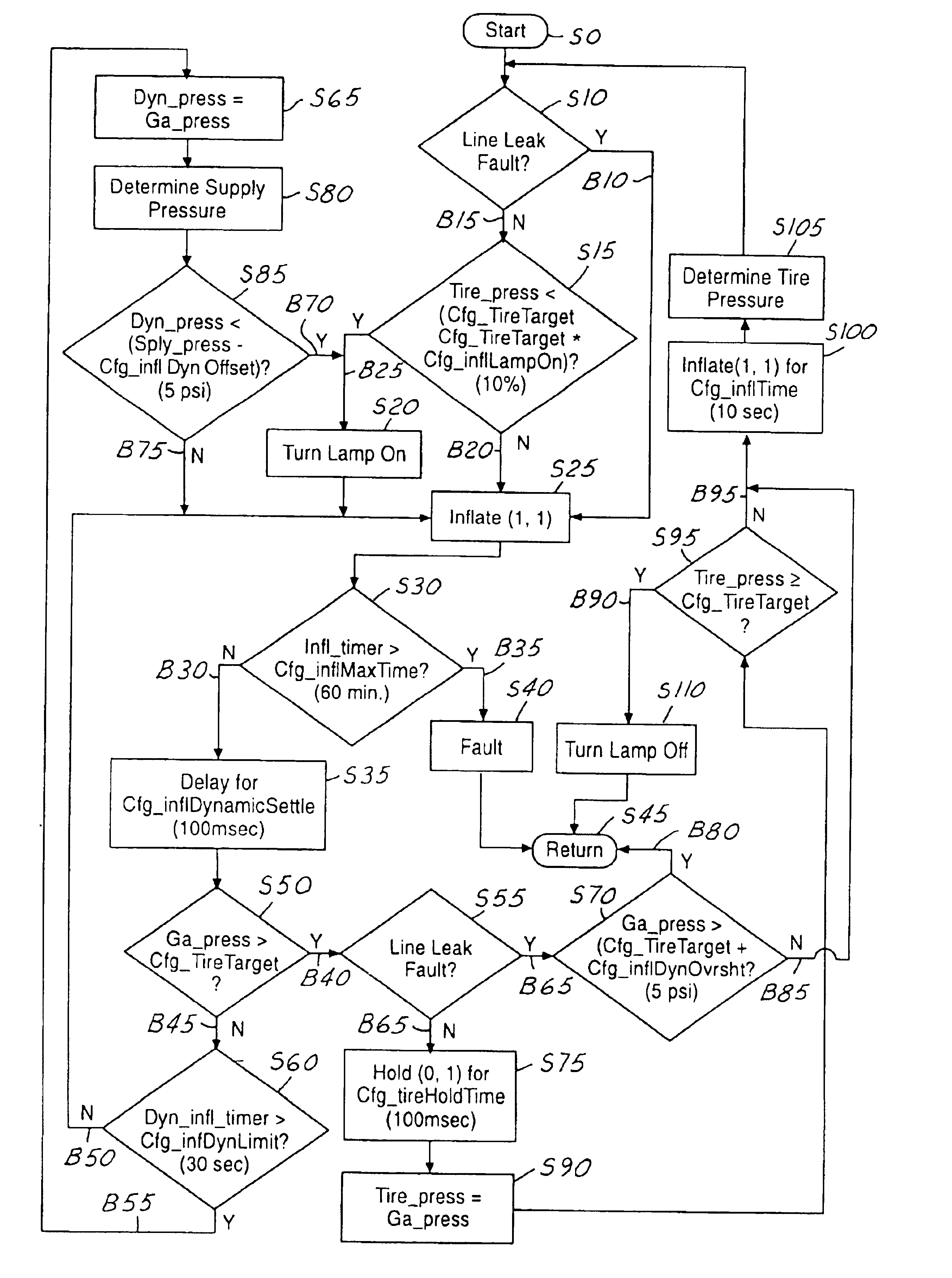
The invention is a method of inflating vehicle tires that minimizes the amount of time needed for same. The method may be achieved with known tire pressure management systems, such as the exemplary tire pressure management system described below.
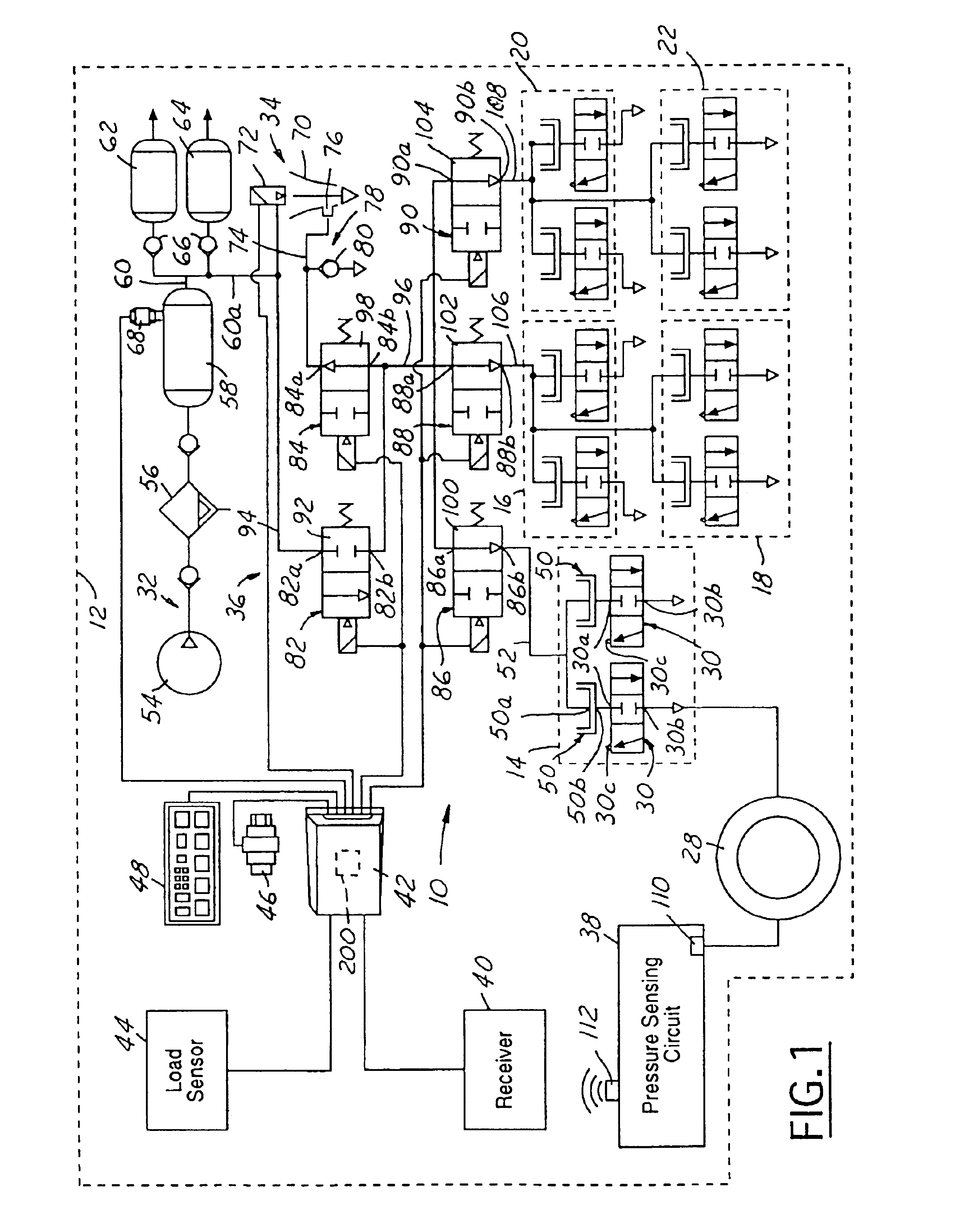
FIG. 1 shows a tire pressure management system 10 for a vehicle 12 for describing, but not limiting applicability of the invention. Vehicle 12 may be, but is not limited to being a tractor-trailer. The system may be used in connection with a wide variety of vehicles, including automobiles.
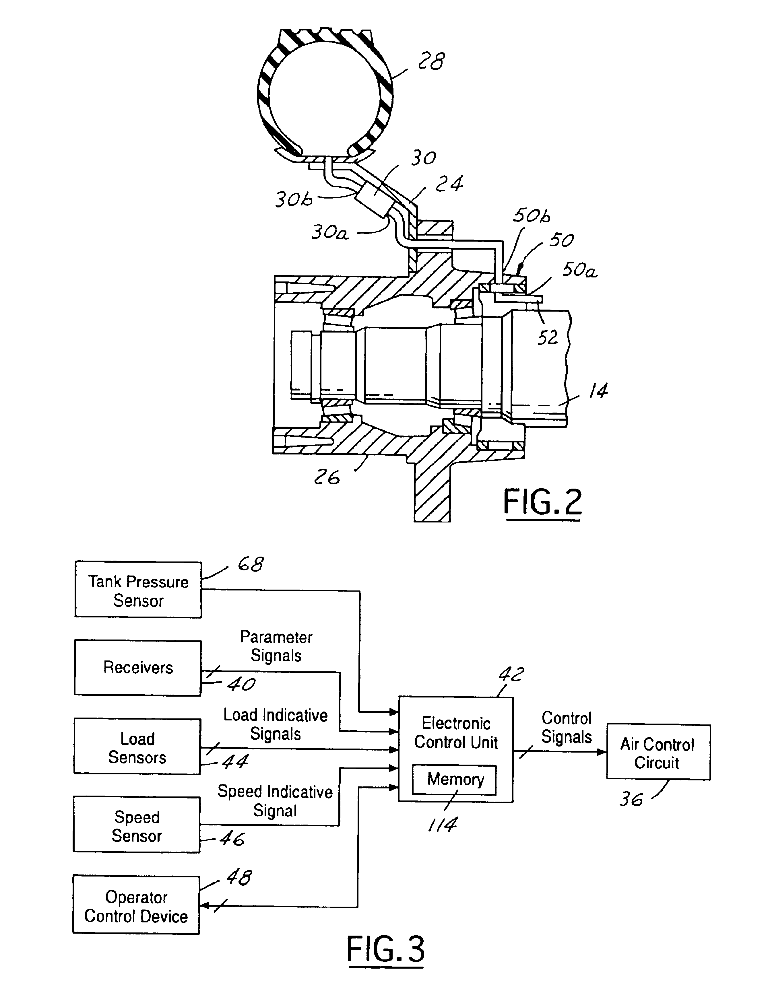
Vehicle 12 may include a plurality of axles, including a steer axle 14, a tandem axle assembly having drive axles 16, 18 and another tandem axle assembly having trailer axles 20, 22. As shown in greater detail in FIG. 2, each axle, such as drive axle 14, may include wheels 24 affixed to wheel hubs 26 disposed at each outboard end of the axle and rotationally supported on axle 14. Each wheel 24 may include one or more inflatable tires 28 mounted thereon.
Syst...
PUM
Abstract
A method of inflating a tire, or vehicle tire, that minimizes the amount of time needed for same is disclosed. The method of inflating a tire with a tire pressure management system includes introducing continuous fluid flow of a fluid into the tire, ascertaining the dynamic pressure of the fluid during said introducing continuous fluid flow, terminating continuous fluid flow when the dynamic pressure exceeds or equals a predetermined amount, and introducing pulsed fluid flow of the fluid into the tire.
Description
BACKGROUND OF HE INVENTIONConventional tire pressure management systems typically have central tire inflation systems (CTI systems), also known as on-board inflation systems and traction systems. These tire pressure management systems are well known, as may be seen by reference to the following U.S. Pat. Nos. 5,516,379; 5,313,995; 5,273,064; 5,253,687; 5,180,456; 5,179,981; 5,174,839; 5,121,774; 4,924,926; 4,922,946; 4,917,163; 4,893,664; 4,883,106; 4,883,105; 4,825,925; 4,782,879; 4,754,792; 4,724,879; 4,678,017; 4,640,331; and 4,619,303. The entire disclosure of each of these patents is incorporated herein.Generally, tire pressure management systems employ a pneumatically controlled wheel valve that is affixed to each vehicle wheel assembly for controlling tire pressure in response to pressure signals from a fluid control circuit. The fluid control circuit is connected to each wheel valve via a rotary seal assembly associated with each wheel valve. In some systems, tire pressure i...
Claims
Application Information
Patent Timeline
Application Date:The date an application was filed.
Publication Date:The date a patent or application was officially published.
First Publication Date:The earliest publication date of a patent with the same application number.
Issue Date:Publication date of the patent grant document.
PCT Entry Date:The Entry date of PCT National Phase.
Estimated Expiry Date:The statutory expiry date of a patent right according to the Patent Law, and it is the longest term of protection that the patent right can achieve without the termination of the patent right due to other reasons(Term extension factor has been taken into account ).
Invalid Date:Actual expiry date is based on effective date or publication date of legal transaction data of invalid patent.