Al technical title is built by PatSnap Al team. It summarizes the technical point description of the patent document.
a welding machine and automatic technology, applied in the direction of lamination, roof tools, decorative arts, etc., can solve the problems of complicated modifications of additional rollers, and achieve the effect of less interference and higher welding speed
Inactive Publication Date: 2005-03-15
LEISTER TECHNOLOGIES
View PDF15 Cites 20 Cited by
Summary
Abstract
Description
Claims
Application Information
AI Technical Summary
This helps you quickly interpret patents by identifying the three key elements:
Problems solved by technology
Method used
Benefits of technology
The axes of the guide wheel and of a pressure roller and driving roller, as pressure and driving device, are arranged parallel to one another. Before the start of welding, the automatic welding machine can be oriented once with the axes perpendicularly to the edge of the top plastic material. It maintains the orientation automatically during the welding operation and the forward movement and drifting-away is prevented. The guide wheel, which in the prior art has only performed a pointer function, has now assumed a guidance function during the forward movement of the automatic welding machine.
During tests, it has surprisingly been found that such an automatic welding machine keeps exactly to the track. At the correct setting, the operator no longer needs to carry out any corrections at all and the automatic welding machine runs along the weld. Consequently, an increased weld quality is obtained and the weld is also clearly improved visually. Fold formation is avoided. Since no further corrections have to be made, the automatic welding machine is also extremely easy to operate.
If the automatic welding machine is provided with transport rollers, so that it can also be easily moved in the transport position and aligned with the welding line, weight must be transferred to the guide wheel in the welding position. To this end, the guide wheel, according to an advantageous configuration, is adjustable in the vertical direction relative to the chassis. This adjustment achieves the effect that, in the transport position, the weight of the chassis lies on the nearest transport roller, preferably a steering roller. In the welding position, the guide wheel takes up the weight of the chassis, the nearest transport roller being raised slightly from the floor.
In the case of a chassis having a lateral chassis arm for the welding device to the side of the guide wheel, a transport steering roller is expediently arranged on the chassis arm in order to support the automatic welding machine and so as to not disturb the straight-ahead running at the same time.
Problems solved by technology
Further modifications by additional rollers are more complicated and do not contribute to the improvement in the principle.
Method used
Image
Click on the blue label to locate the original text in one second.
Reading with bidirectional positioning of images and text.
Examples
Embodiment Construction
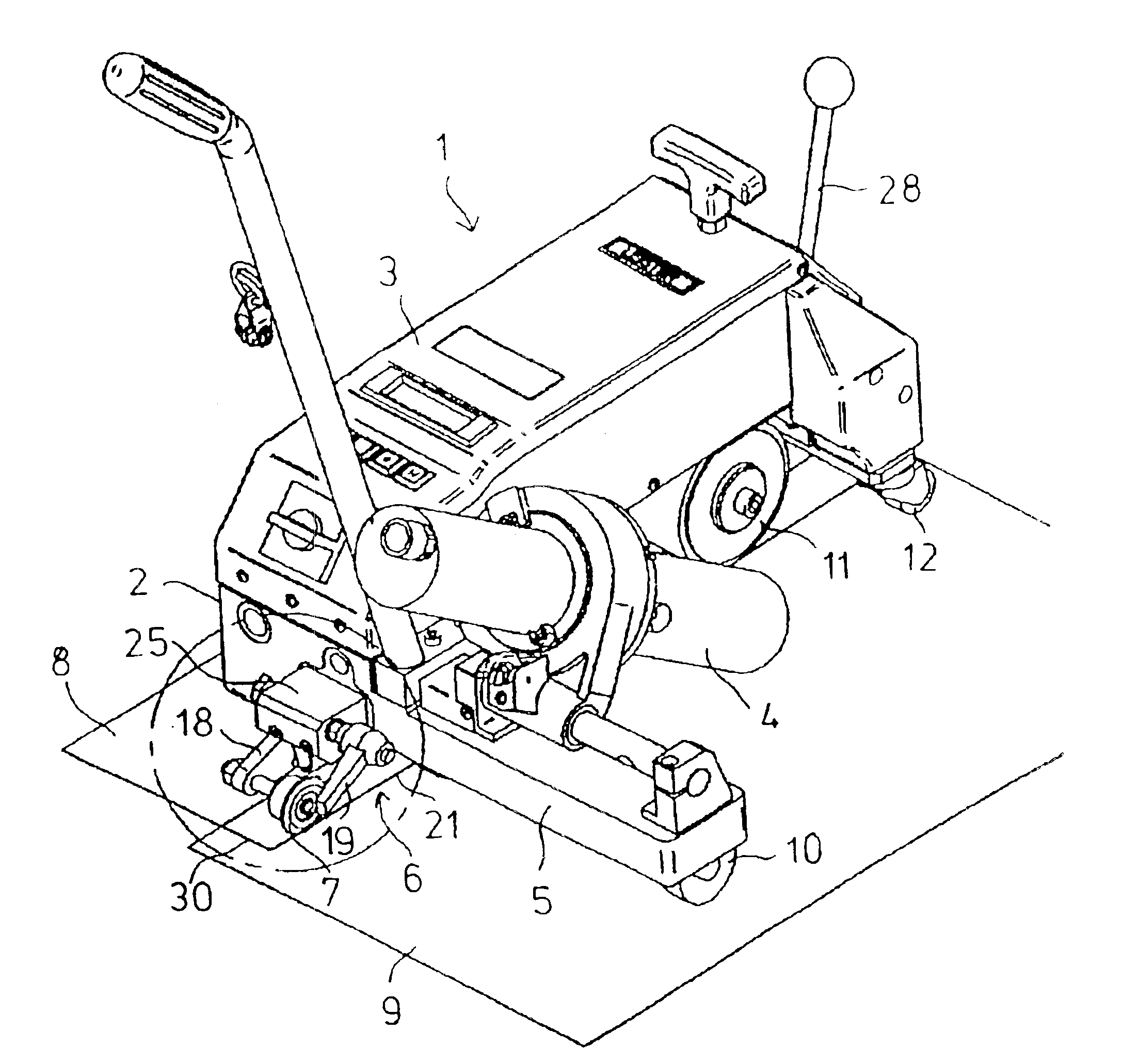
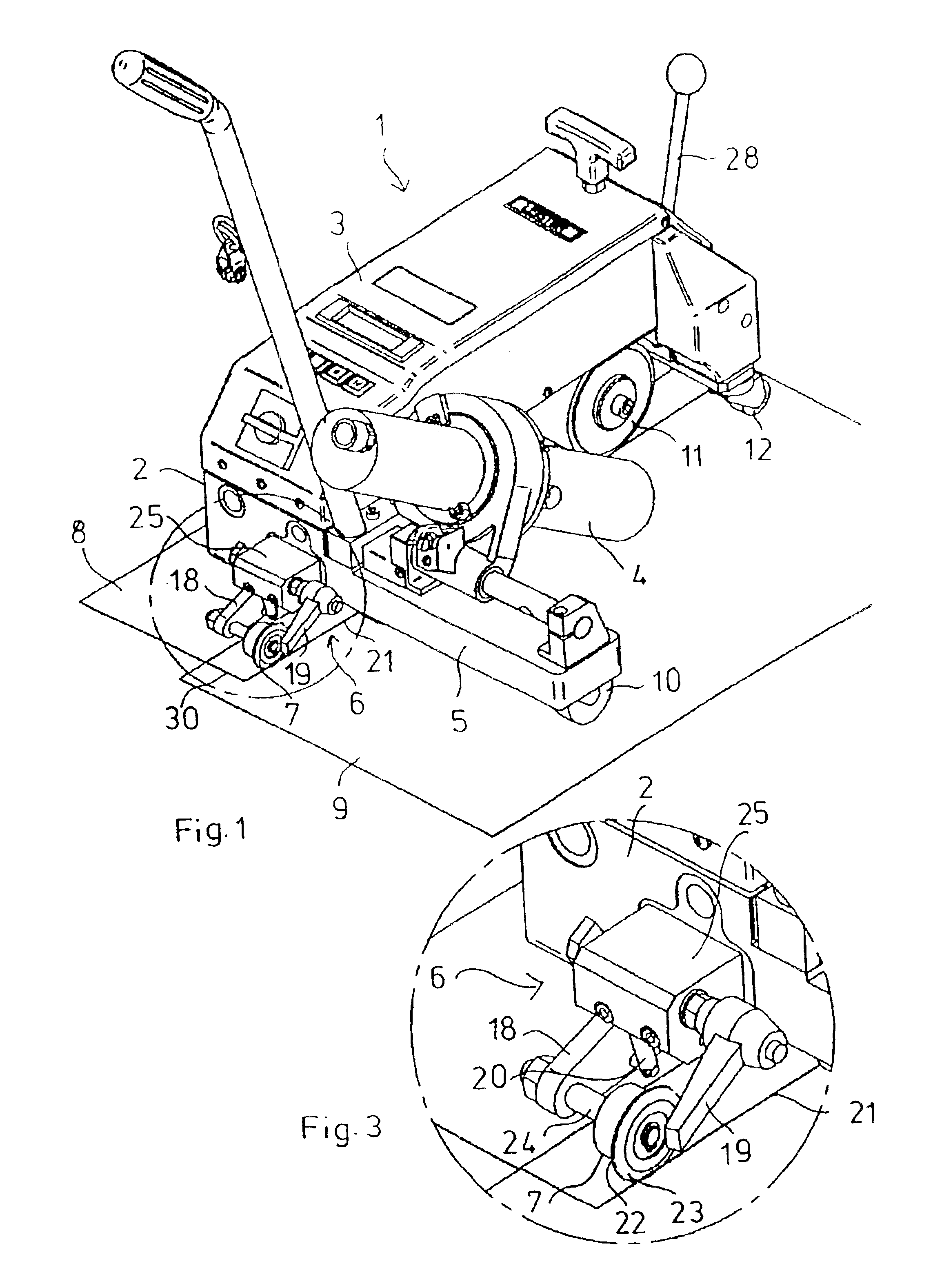
FIG. 1 shows the automatic welding machine 1 with the chassis 2 which carries the housing 3 with the drive unit and the welding device 4 on a lateral chassis arm 5. Located in front of the chassis 2 is a guide device 6 having a guide wheel 7 which runs along the edge 21 of a top tarpaulin 8 which is to be welded to a bottom tarpaulin 9. The driving and pressure roller 11 runs essentially on the overlap region 30 (weld region) of the tarpaulins 8 and 9. In this welding position, the automatic welding machine 1 is carried by the guide wheel 7, the transport roller 10 on the chassis arm 5, and the driving and pressure roller 11. Arranged in the rear region are further transport rollers 12, 13, which can be brought from a transport position into a welding position by means of the lever 28 and lift the driving and pressure roller 11 from the floor in the transport position.
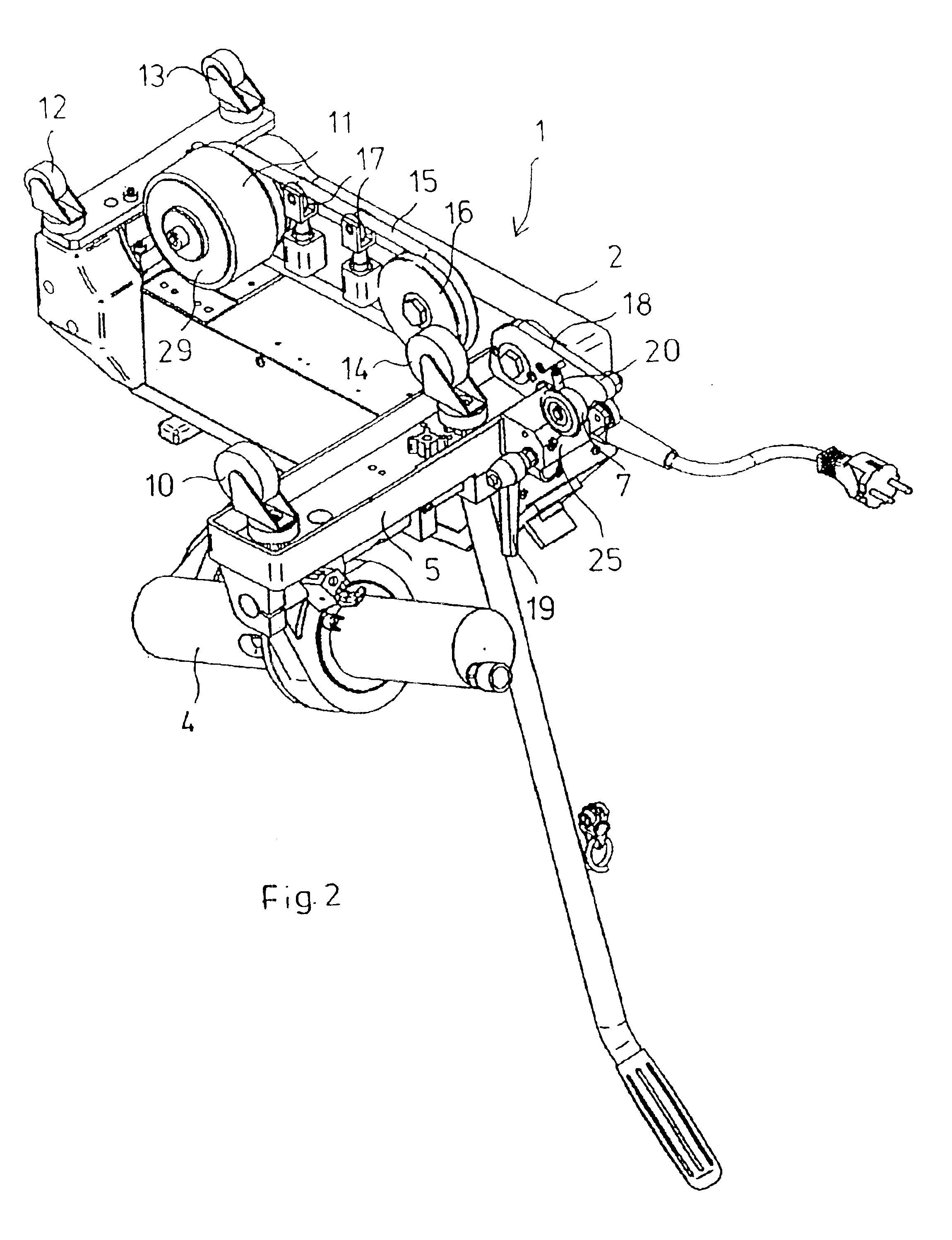
FIG. 2 shows the underside of the chassis 2 with the transport rollers12, 13 in the rear region and the transport ro...
PUM
Property
Measurement
Unit
rotation axis
aaaaa
aaaaa
(planar) plastic
aaaaa
aaaaa
weight
aaaaa
aaaaa
Abstract
An automatic welding machine for planar plastic materials, such as sealing sheets, tarpaulins or films, the chassis, in the welding position, in addition to being carried by the driving unit and the pressure device, also being carried by a rigid guide wheel, preferably in the front region of the chassis. With respect to a pressure roller running essentially on the welded overlap region, the guide wheel is arranged in such a way that, during the welding, it runs along the bottom plastic material parallel to the edge of the top plastic material. In addition, the guide wheel has a narrow running surface. During the welding, the guide wheel runs along the edge of the overlapping plastic material and the pressure roller runs essentially on the weld region. Due to this configuration, the automatic welding machine can follow the edge in such a way as to keep to the track, so that guidance by the operator or frequent corrections of the welding direction are not necessary. This leads to an increased weld quality and also to a higher welding speed. There is less interference from the background or due to the welding device swinging in laterally.
Description
BACKGROUND OF THE INVENTIONThe present invention relates to an automatic welding machine for planar plastic materials, having a chassis and, arranged thereon, a welding device, a driving unit, a pressure device for the materials welded in an overlapping manner.Such automatic welding machines are generally known and are in use, and are used for welding tarpaulins of coated fabrics, films and sealing sheets of PVC-P, PE, ECB, CSPE, EPDM, PVDF, etc., and also PE-coated band fabrics for trucks, tents, covers in agriculture, biotopes, swimming pools, awnings, boat tarpaulins, inflatable boats, advertising tarpaulins, etc. Further similar materials occur in civil engineering, roof construction and flooring. These materials are referred to below as (planar) plastic materials. The plastic materials are arranged in an overlapping manner for welding, so that the two plastic materials lie one on top of the other in an overlap region and are referred to as a top plastic material and as a bottom...
Claims
Application Information
Patent Timeline
Application Date:The date an application was filed.
Publication Date:The date a patent or application was officially published.
First Publication Date:The earliest publication date of a patent with the same application number.
Issue Date:Publication date of the patent grant document.
PCT Entry Date:The Entry date of PCT National Phase.
Estimated Expiry Date:The statutory expiry date of a patent right according to the Patent Law, and it is the longest term of protection that the patent right can achieve without the termination of the patent right due to other reasons(Term extension factor has been taken into account ).
Invalid Date:Actual expiry date is based on effective date or publication date of legal transaction data of invalid patent.