Marine shaft seal with lip seal, bearing and gasket

Inactive Publication Date: 2005-03-15
DURAMAX MARINE
View PDF33 Cites 46 Cited by
  • Summary
  • Abstract
  • Description
  • Claims
  • Application Information

AI Technical Summary

Benefits of technology

In accordance with the preferred embodiments of the present invention, there is provided a shaft seal system for use with a vessel, such as a recreational or noncommercial water vessel (or in some instances small commercial vessels such as some fishing boats), where the drive, or propeller shaft extends from an inboard engine to gear box, through the hull or bulkhead, to an outboard drive means, such as a propeller. The shaft seal system prevents the flow of water through the opening in the hull or bulkhead, into the vessel and out of the confines of the system. Considering the system from aft to forward, there is provided an appropriate adapter that fills the hull opening, and which is connected to a seal housing which is connected to a sea gasket or diaphragm, which in turn is connected to a lip seal flange attachment. The seal housing has a lip seal, which will be discussed in greater detail below, and the lip seal flange attachment is a rearwardly extending body which goes around the shaft. The sea gasket is attached to the seal housing and there is a compression ring therebetween to stabilize the sea gasket during operation of the propeller drive shaft. The seal housing is held in place with the sea gasket by a mini tie lock and the sea gasket is held in place between the compression ring and the lip seal flange attachment by threaded screws or the like.

Problems solved by technology

This is an important feature because one of the causes of catastrophic failures of the prior art devices, other than that of MacDonald '098, is that they constituted a fully rigid device with no resilient components.

Method used


Image

  • Marine shaft seal with lip seal, bearing and gasket
  • Marine shaft seal with lip seal, bearing and gasket
  • Marine shaft seal with lip seal, bearing and gasket

Examples


Embodiment Construction

The present invention is now described with reference to the drawings, wherein like reference numerals are used to refer to like elements throughout. In the following description, for purposes of explanation, numerous specific details are set forth in order to provide a thorough understanding of the present invention. It will be evident, however, to one skilled in the art that the present invention may be practiced without these specific details.

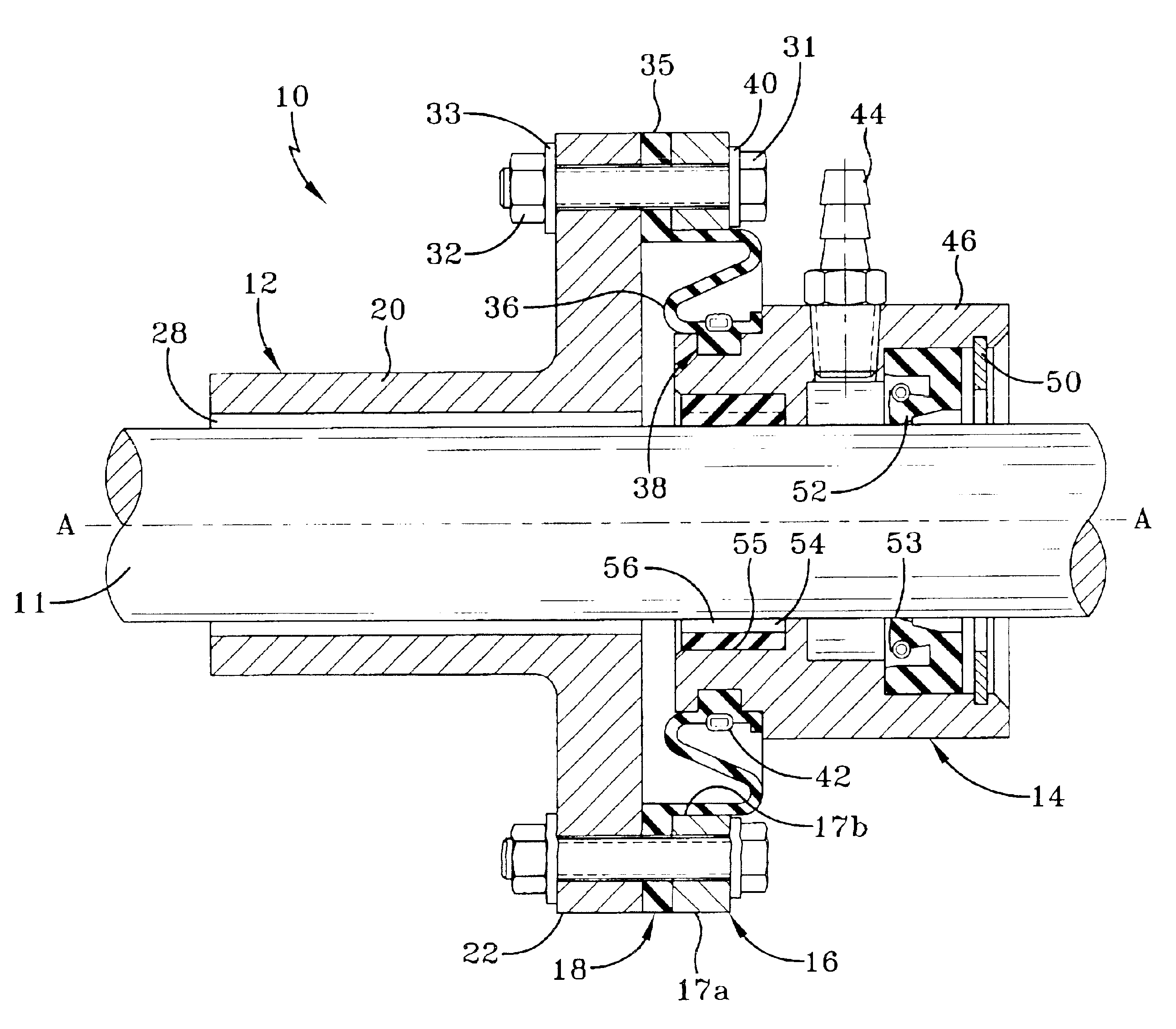
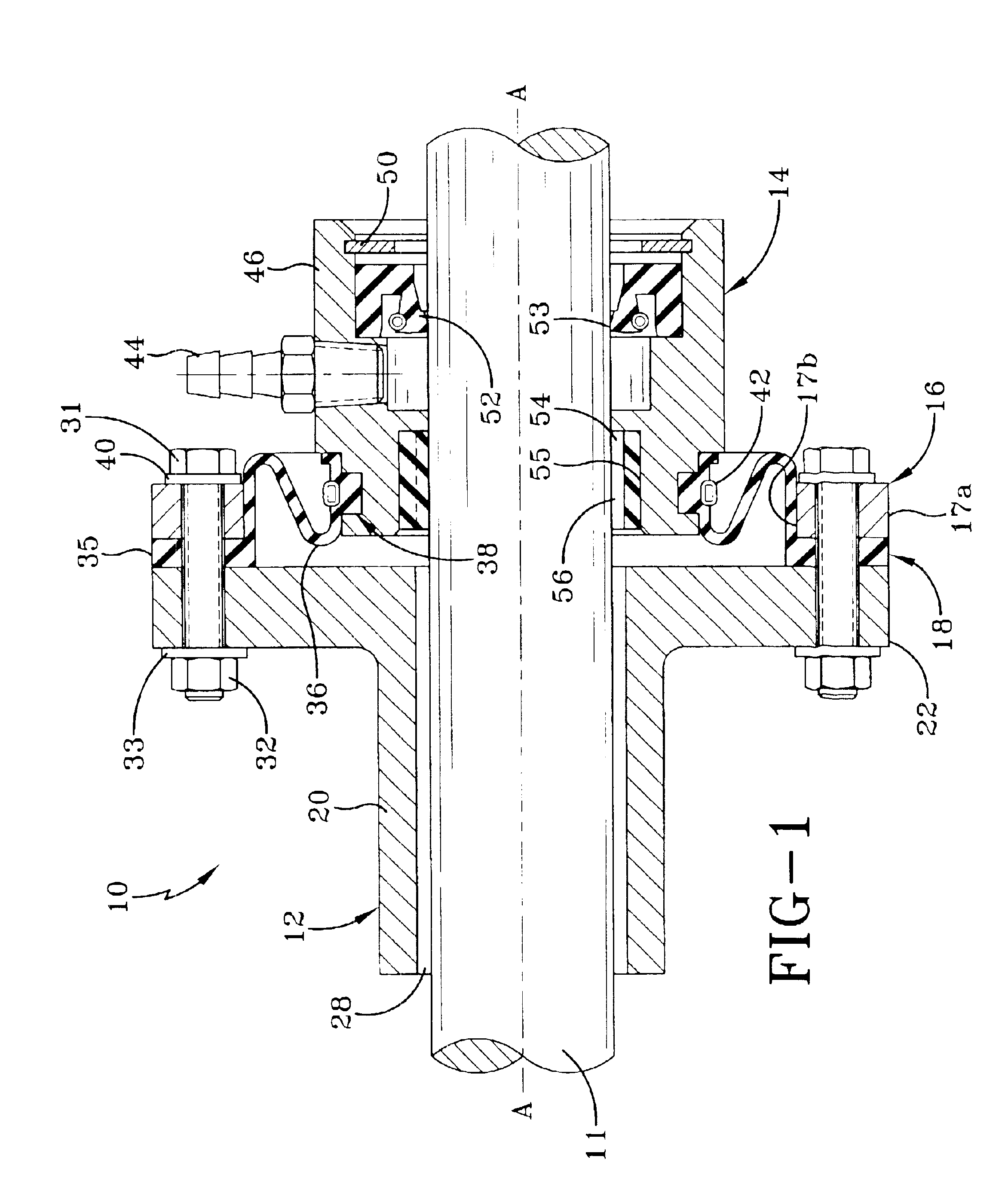
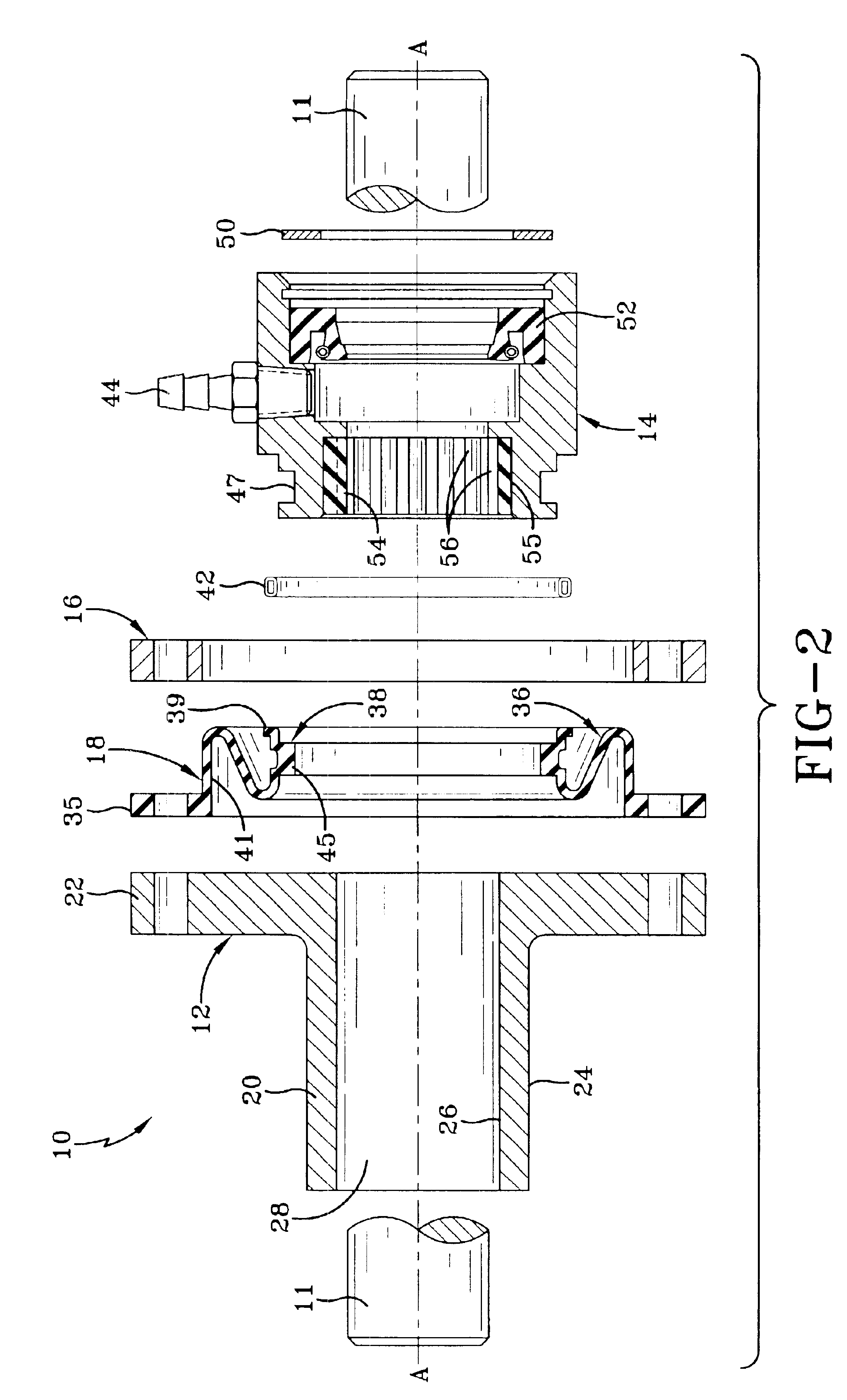
Turning now to FIGS. 1 and 2, the shaft-sealing device of the present invention is shown and referred to generally at numeral 10. Shaft sealing device 10 is intended to provide a seal to prevent fluid, such as seawater, from entering the hull of a vessel. A propeller shaft 11 of the vessel is connected to the engine (not shown) of the vessel at one end and a propeller (not shown) of the vessel at the other end. Shaft sealing device 10 comprises a lip seal flange attachment 12, a seal housing 14, a compression ring 16 and a diaphragm or sea g...


PUM


Abstract

A sealing device for use with a drive shaft of a water vessel. The sealing device comprises a housing for a seal and bearing, a compression ring, a lip seal flange attachment and a diaphragm for tracking the movement of the shaft. The diaphragm is made of a resilient, flexible material and is operatively connected to the seal housing. In operation, the diaphragm tracks the motion of the drive shaft so that the drive shaft may move freely in the hull of the vessel. The diaphragm allows the rigid seal housing to also move in response to any axial, lateral or circular-axial (wobble-like) movement of the shaft so that a constant seal around the shaft is provided.

Description

FIELD OF THE INVENTIONThe present invention relates generally to a device for creating a fluid-tight seal around a rotatable shaft and a structure through which the shaft passes. More specifically, the present invention relates to a watertight seal between the propeller drive shaft in a water vessel and an aperture in the hull of the vessel through which the shaft passes.DESCRIPTION OF THE PRIOR ARTWatertight seals through which pass a rotatable shaft are routinely used with water vessels. Such seals must be used to retain water on one side of the vessel. For example, a propeller drive shaft extends from the interior of the hull of the vessel to the exterior fluid environment, and passes through the aperture in the hull of the boat. It is imperative that the aperture is sealed in order to prevent water from entering the hull of the vessel through the aperture.One method commonly used in the art is the use of a stuffing box. Stuffing boxes generally consist of a bronze or other metal...

Claims


Application Information

Patent Timeline
Patent Type & Authority Patents(United States)
IPC IPC(8): F16J15/32
CPCF16J15/3276F16J15/3224
Inventor MACDONALD, GEORGE
Owner DURAMAX MARINE
Why Eureka
Try Eureka