Tire design based on first principles of structural engineering
a technology of structural engineering and tire design, applied in the field of tire construction and tire making, can solve the problems of slow and even wear, and achieve the effect of improving the overall wear, handling, rolling resistance and traction properties of the tir
- Summary
- Abstract
- Description
- Claims
- Application Information
AI Technical Summary
Benefits of technology
Problems solved by technology
Method used
Image
Examples
example 1
In order to evaluate the new concept tire, finite element analyses (FEA) were conducted to compare the new tire to a selected, well-performing control tire. The strain energy densities (SED) in the tire were compared since the SED reflects the combined values of the three normal stresses, three shear stresses, and their strains. Tables 1 and 2 show the computed results for the control and the new concept tires.
A production tire, size P185 / 70 R14, was used as a control, for comparison with the properties of the same size experimental tire, made using the method of the invention. The stresses, strains, and rolling resistance contributions of various components of the tire were calculated.
The control tire and the experimental tire were set up with the same cord angles, the same green ends per centimeter (e.p.c.) (ends per inch (e.p.i.)), and the same materials. Table 1 also shows that the experimental tire showed less deflection than the control tire.
TABLE 1Computed Tire Response for 2...
example 2
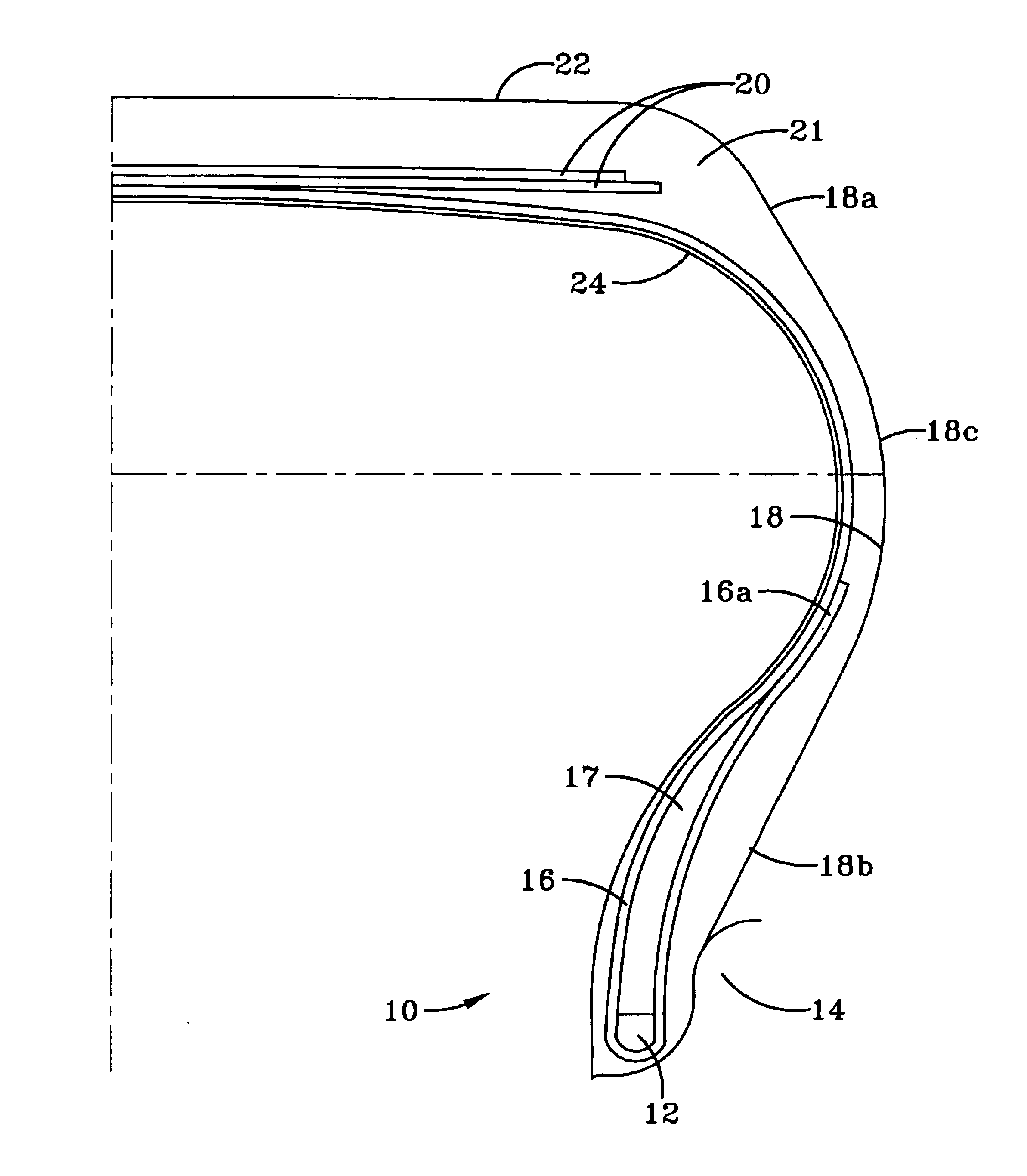
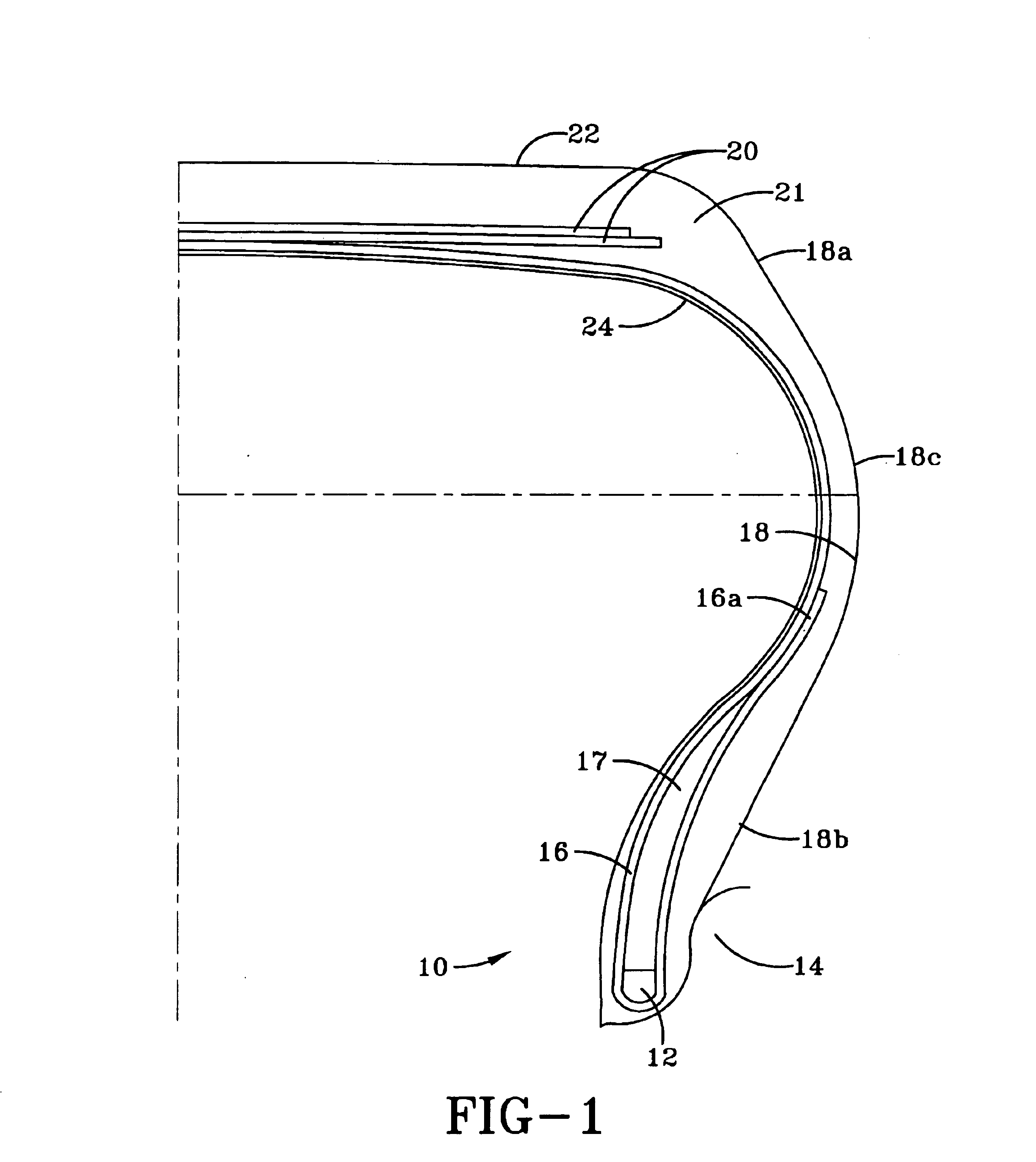
Twelve control tires and twelve tires of the invention were built and tested for rolling resistance using the standard rolling resistance tests. The tires were constructed using the same materials, and differed only in that: the apex in the experimental tires was 6.35 cm (2 inches) high, and was absent in the control tire; the turn-up ply in the experimental tire extended 6.35 cm (2.5 inches) above the tire / rim interface, whereas the control tire had a turn-up of 1.78 cm (0.7 inch); a sidewall wedge in the experimental tire, in a portion below the first belt extended 5.79 cm (2.28 inches) as compared to a conventional wedge extending 1.22 cm (0.48 inch) in the control tire, and had a thickness below the edge of the first belt of 0.61 cm (0.24 inch) as compared to 0.13 cm (0.05 inch) in the control tire. The results are summarized in Table 4.
TABLE 4ControlExperimental185 / 7OR14185 / 7OR14RollingRollingTireWeightResistanceWeightResistanceSizeKg (lbs)N (lbs)Kg (lbs)N (lbs)7.76(17.07)35.9(...
example 3
Eight tires of each construction illustrated in Example 2 were tested for durability using the standard Fatigue Capacity test (FatCap). The results, summarized in Table 8, indicate a 22% improvement in durability of the experimental tire.
TABLE 8ControlExperimentalFatigue Capacity Test185 / 70R14185 / 70R14T&RA Rated Load at 23.8Npscm, 545.9 Kg(35 psi, 1201 lbs)Fatigue Capacity1397.71701.6
PUM
| Property | Measurement | Unit |
|---|---|---|
| diameter | aaaaa | aaaaa |
| cord angles | aaaaa | aaaaa |
| angle | aaaaa | aaaaa |
Abstract
Description
Claims
Application Information
 - R&D
- Intellectual Property
- Life Sciences
- Materials
- Tech Scout
- Unparalleled Data Quality
- Higher Quality Content
- 60% Fewer Hallucinations
Browse by: Latest US Patents, China's latest patents, Technical Efficacy Thesaurus, Application Domain, Technology Topic, Popular Technical Reports.
© 2025 PatSnap. All rights reserved.Legal|Privacy policy|Modern Slavery Act Transparency Statement|Sitemap|About US| Contact US: help@patsnap.com


