Display device

a display device and display case technology, applied in the field of display cases, can solve problems such as the reduction of manufacturing costs

Inactive Publication Date: 2005-03-15
SHARP KK
View PDF7 Cites 89 Cited by
  • Summary
  • Abstract
  • Description
  • Claims
  • Application Information

AI Technical Summary

Benefits of technology

In view of the problems mentioned above, an object of the present invention is to provide a display device capable o...

Problems solved by technology

In addition, since the chassis is dispensed with, a smaller number of components...

Method used


Image

  • Display device
  • Display device
  • Display device

Examples


first embodiment

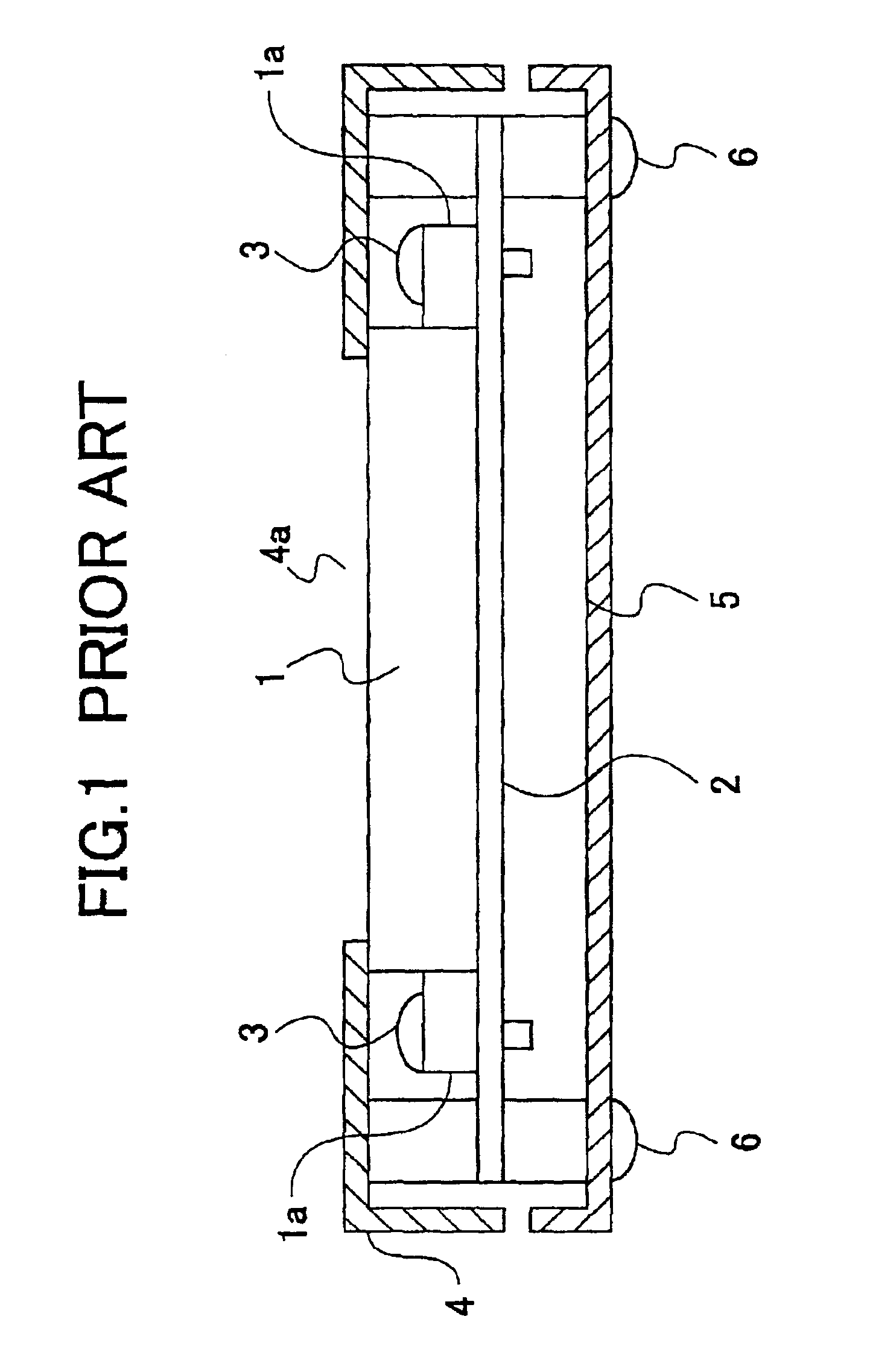
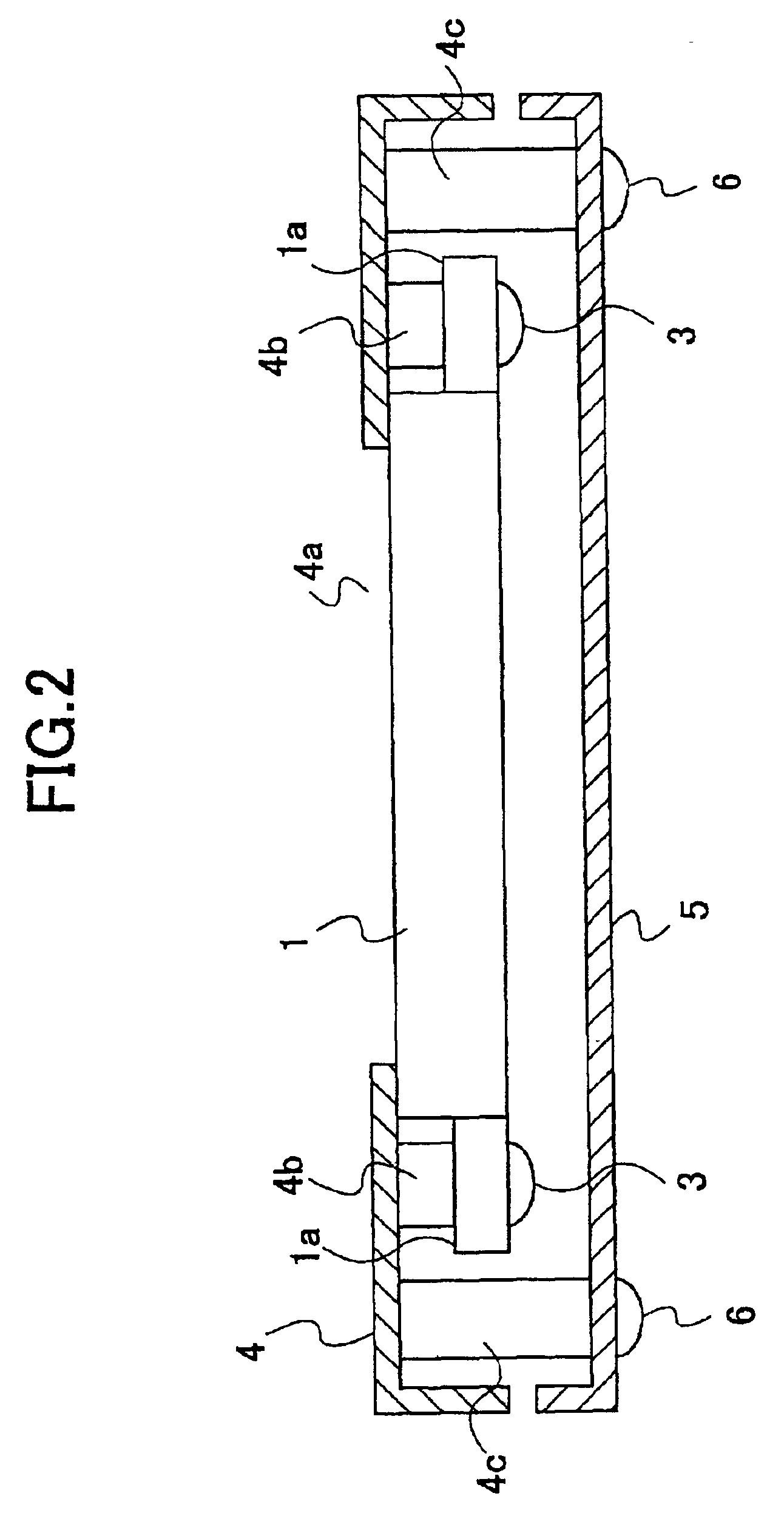
FIG. 2 is a cross-sectional view of a liquid crystal display device according to the present invention. The housing of the liquid crystal display device shown in FIG. 2 comprises a display face cover 4 corresponding to an upper housing and a rear cover 5 corresponding to a lower housing. An opening 4a is formed in the display face cover 4 and the display portion of the liquid crystal display unit 1 is exposed through the opening 4a.

The liquid crystal display unit 1 comprises a liquid crystal element and a backlight device and is configured such that the liquid crystal display element is mounted relative to the housing of the backlight device. The backlight device projects light from the backside of the liquid crystal display element so as to make visible the display on the liquid crystal display element, is mounted to the housing, and has a light source such as a fluorescent lamp.

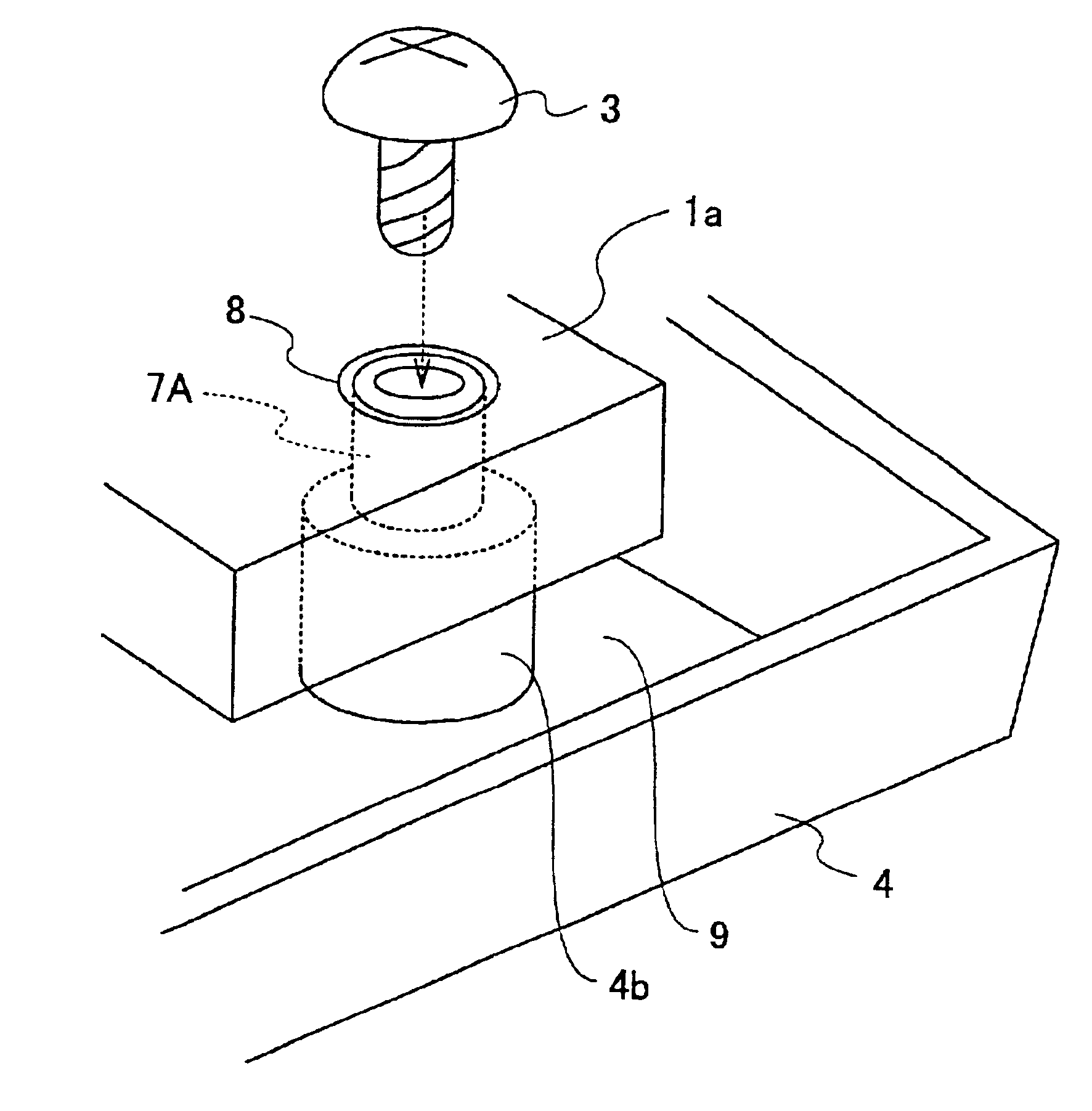
According to the first embodiment of the present invention, a mounting portion 1a extending from the ho...

second embodiment

In short, in the second embodiment according to the present invention shown in FIG. 5, the rear cover 5 corresponding to the lower housing is mounted to the display face cover 4 through the mounting portion 1a of the liquid crystal display unit 1. In this case, a boss portion 5a is formed integrally inside the rear cover 5 and a perforation is formed in the boss portion 5a into which a screw 6 is to be inserted.

The screw 6 is inserted into the perforation from the exterior side of the rear cover 5, penetrates the perforation in the mounting portion 1a, reaches the boss portion 4b of the display face cover 4, and is finally screwed into the screw hole formed in the boss portion 4b. It is noted that in the second embodiment according to the present invention, the positioning of the liquid crystal display unit 1 relative to the display face cover 4 is achieved by the same configuration of the positioning pin and the positioning hole as described in the above-mentioned first embodiment....


PUM


Abstract

A liquid crystal display unit having a liquid crystal display element is accommodated in a housing having an opening for exposing the display portion of the display element to the exterior. The housing comprises a display face cover and a rear cover and the liquid crystal display unit is mounted directly relative to the display face cover. A positioning pin is provided so as to extend out from the display face cover in order to position the liquid crystal display unit relative to the display face cover, and a positioning hole, which engages the positioning pin, is provided on the liquid crystal unit.

Description

BACKGROUND OF THE INVENTION1. Field of the InventionThe present invention relates to a display device, and in particular to a display device having a display element incorporated within the housing of the display device.2. Description of the Related ArtFIG. 1 is a cross-sectional view of a conventional liquid crystal display device having a liquid crystal display element incorporated therein. In the conventional liquid crystal display device shown in FIG. 1, a liquid crystal display unit 1 having a liquid crystal display element incorporated is mounted to a chassis 2 using screws 3. The chassis 2 is mounted to a display face cover 4 in such a manner that the display portion of the liquid crystal display unit 1 is situated at an opening 4a of the display face cover 4. At the same time, a rear cover 5 is also mounted to the chassis 2. In short, the display face cover 4 and the rear cover 5 are fixed to each other, having the chassis 2 in between themselves, by inserting screws 6 from ...

Claims


Application Information

Patent Timeline
IPC IPC(8): G02F1/13G02F1/1333G02F1/13357G09F9/00H05K5/02H05K7/12
CPCG02F1/133308G02F2001/133322G02F1/133322G02F1/1333
Inventor EIRAKU, TAKAYUKIHAYASHIMOTO, SEIJI
Owner SHARP KK
Why Eureka
Try Eureka