Coded data output device and method

a data output device and data output technology, applied in the field of encoded data output devices and methods, can solve problems such as overflow or underflow in the decode buffer

Inactive Publication Date: 2005-03-15
SONY CORP
View PDF16 Cites 12 Cited by
  • Summary
  • Abstract
  • Description
  • Claims
  • Application Information

AI Technical Summary

Benefits of technology

[0008]Encoding information includes the size of generated codes for each encoding processing unit, and the size of encoded data to be output is controlled according to the size of generated codes, thereby constantly controlling a delay from the buffer means to the buffer of decoding side to which the encoded data is output. Therefore, it is possible to prevent the buffer of decoding side from failing if the transmission rate is varied according to the size of generated codes.

Problems solved by technology

However, in the digital broadcasting system which transmits encoded data at a fixed rate, overflow or underflow occurs in a decode buffer if the transmission rate is variable for transmission.

Method used


Image

  • Coded data output device and method
  • Coded data output device and method
  • Coded data output device and method

Examples


Embodiment Construction

ing the transmission plan of video data subjected to pull-down processing.

[0021]FIG. 13 is a schematic diagram explaining the transmission plan of video data subjected to pull-down processing.

[0022]FIG. 14 is a schematic diagram showing the size of encoded data to be transmitted for each frame which is determined by the transmission plan.

[0023]FIG. 15 is a schematic diagram explaining the transmission start timing based on the transmission plan.

BEST MODE FOR CARRYING OUT THE INVENTION

[0024]One embodiment of the present invention will be described in detail by referring to the drawings.

[0025](1) The Whole Construction

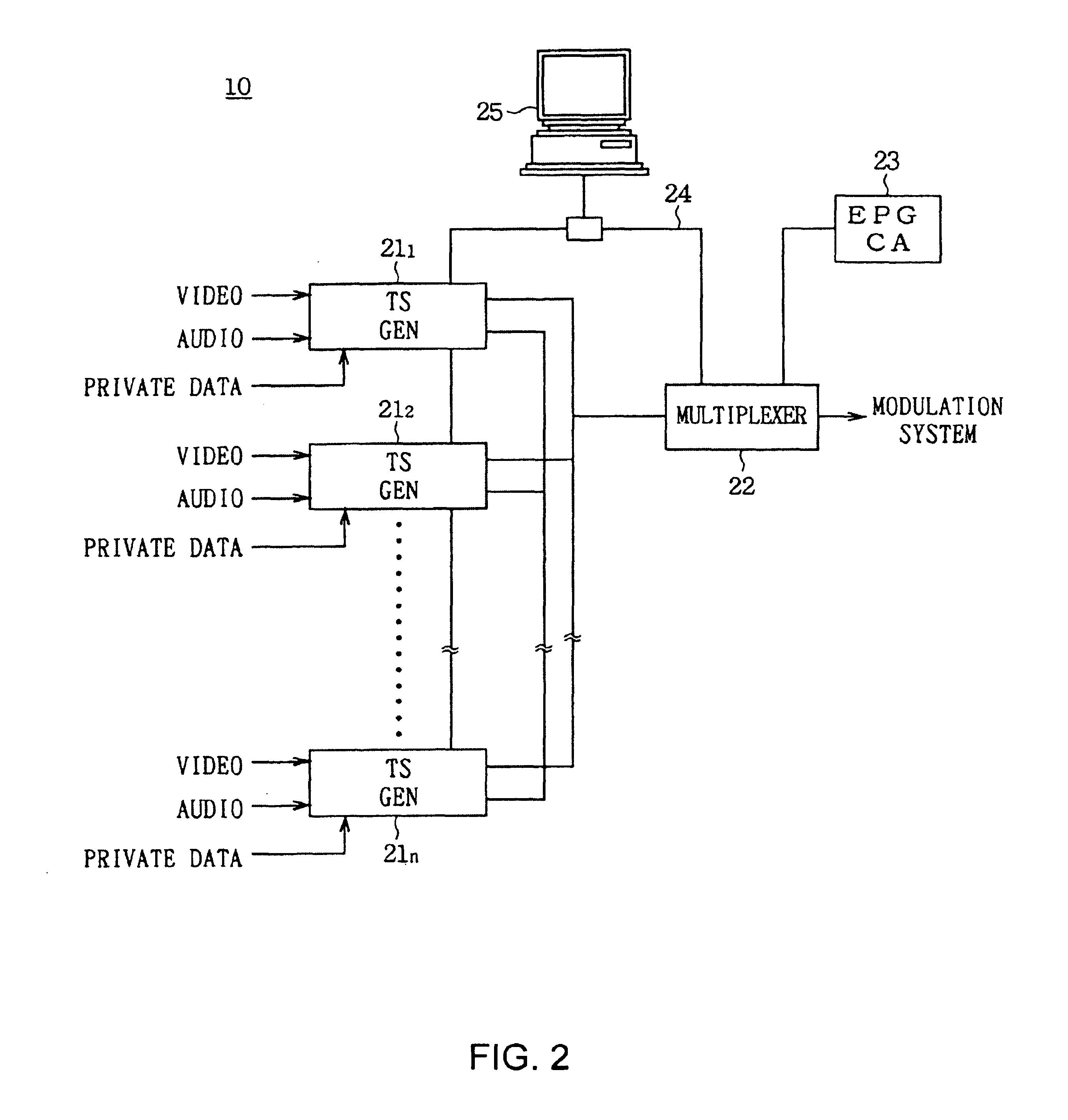
[0026]FIG. 2 shows the constitution of an encoding system 10, in which each transport stream generating apparatus 211, 212, . . . , 21n for n-channels receives video data, audio data, and private data (additional data), and encodes them in the MPEG2.

[0027]Each transport stream generating apparatus 211, 212, . . . , 21n calculates an encoding difficulty degree which varie...


PUM


Abstract

With respect to change of a bit rate at the time of transmitting encoded data TS, a system delay is fixed and the output size of data frame_bit [j] every predetermined data unit is successively calculated, thereby making it possible to continuously obtain data from the buffer 103 of a decoding side without breaks irrespective of change of the bit rate.

Description

TECHNICAL FIELD[0002]The present invention relates to an encoded data outputting apparatus and method, and more particularly, is preferably applicable to an encoded data outputting apparatus and method for multiplexing and transmitting video data and audio data.BACKGROUND ART[0003]Heretofore, in a digital broadcasting system, as shown in FIG. 1, video data is compression-encoded in the MPEG (Moving Picture Experts Group) scheme with a video encoder 1, compression-encoded data ES is stored in an encoder FIFO2 and then transmitted to a decode buffer 3 of a decoding side as a transport stream TS. The decoder 4 reads out data which is stored in the decode buffer 3, at predetermined timing and decodes it.[0004]In such a digital broadcasting system, approximately equivalent encoded data is transmitted to the decode buffer 3 every predetermined timing, thereby preventing the decode buffer 3 from overflow or underflow.[0005]However, in the digital broadcasting system which transmits encoded...

Claims


Application Information

Patent Timeline
Patent Type & Authority Patents(United States)
IPC IPC(8): H04N7/24G10L19/14H04N7/12H04N7/52H04N19/00H04N19/115H04N19/126H04N19/134H04N19/146H04N19/152H04N19/159H04N19/169H04N19/196H04N19/423H04N19/463H04N19/503H04N19/51H04N19/577H04N19/61H04N19/625H04N19/70H04N19/91H04N21/234H04N21/236H04N21/44
CPCH04N7/52H04N21/23406H04N21/236H04N19/152H04N19/15H04N19/61H04N19/14H04N21/44004G10L19/24
Inventor MIYAZAWA, SATOSHI
Owner SONY CORP
Why Eureka
Try Eureka