System and method for energy usage curtailment

a technology of energy usage and curtailment, applied in the direction of mechanical power/torque control, resistance welding apparatus, ratio control, etc., can solve the problems of energy management and energy cost management, difficult for a residence to efficiently and effectively manage energy usage on its own, and generally not precise in maintaining

Inactive Publication Date: 2005-03-15
ITRON
View PDF27 Cites 481 Cited by
  • Summary
  • Abstract
  • Description
  • Claims
  • Application Information

AI Technical Summary

Benefits of technology

The present invention affords a system and method for performing energy usage management within a network. The system may include an energy management device, such as a thermostat device, that may be associated with an energy consuming entity, such as a residence. A server may be remotely located from the energy consuming entity and may perform one or more energy curtailment management operations within the network. The server may be in communication with the energy management system over the network. One or more software applications may be stored thereon for remotely controlling the energy management system in accordance with a particular energy curtailment management operation. Additionally, a database may be associated with the server for storing curtailment event information relating to the network.

Problems solved by technology

Energy management and energy cost management has always been an issue for many residents because of the increasing cost of energy.
However, due to conventional energy management devices, such as thermostats and the like, it can be difficult for a residence to efficiently and effectively manage energy usage on its own.
Unfortunately, conventional thermostat systems, while capable of maintaining a desired temperature in the residence, are not generally precise in maintaining a particular temperature and thus fluctuate through a temperature range.
This fluctuation can result in varying energy consumption, and variable energy cost, just to maintain a particular temperature in the residence over time.
During peak energy demand periods, utilities and service providers are often forced to purchase short-term energy resources at prices that are significantly higher than average and pass on the high costs to its energy customers.
Failure of utilities and service providers to maintain adequate energy resources can lead to power outages that affect the general public and can tarnish the reputation of the utilities and service providers and adversely affect their business.
As a result, utility and service providers often lose millions of dollars every day in order to maintain adequate energy resources.
However, due to the high volatility of wholesale energy prices and the absence of energy management systems for determining real-time information tracking energy usage, consumer participation in reduction compensation programs is limited.
Unfortunately, current curtailment programs lack historical data relating to high cost energy consumption by consumers, and do not rapidly inform consumers of peak energy demand periods.
Thus, consumers generally are not afforded a cost savings benefit by participating in curtailment programs.
Moreover, since wholesale power markets are ordinarily highly volatile, delays and notice periods can cause mismatches between the cost of energy actually purchased by the consumer and the market value of that purchased energy.
Further, conventional curtailment systems typically notify consumers of peak energy demand periods by broadcast facsimile or telephone messages, and conventional curtailment program administration does not currently support grouping consumers by program design, likely response, load zone, or other means.
Conventional curtailment systems also do not provide the capability for both a service provider operator and a consumer user to view, in real-time, the results of participating in an energy reduction program.

Method used


Image

  • System and method for energy usage curtailment
  • System and method for energy usage curtailment
  • System and method for energy usage curtailment

Examples


Embodiment Construction

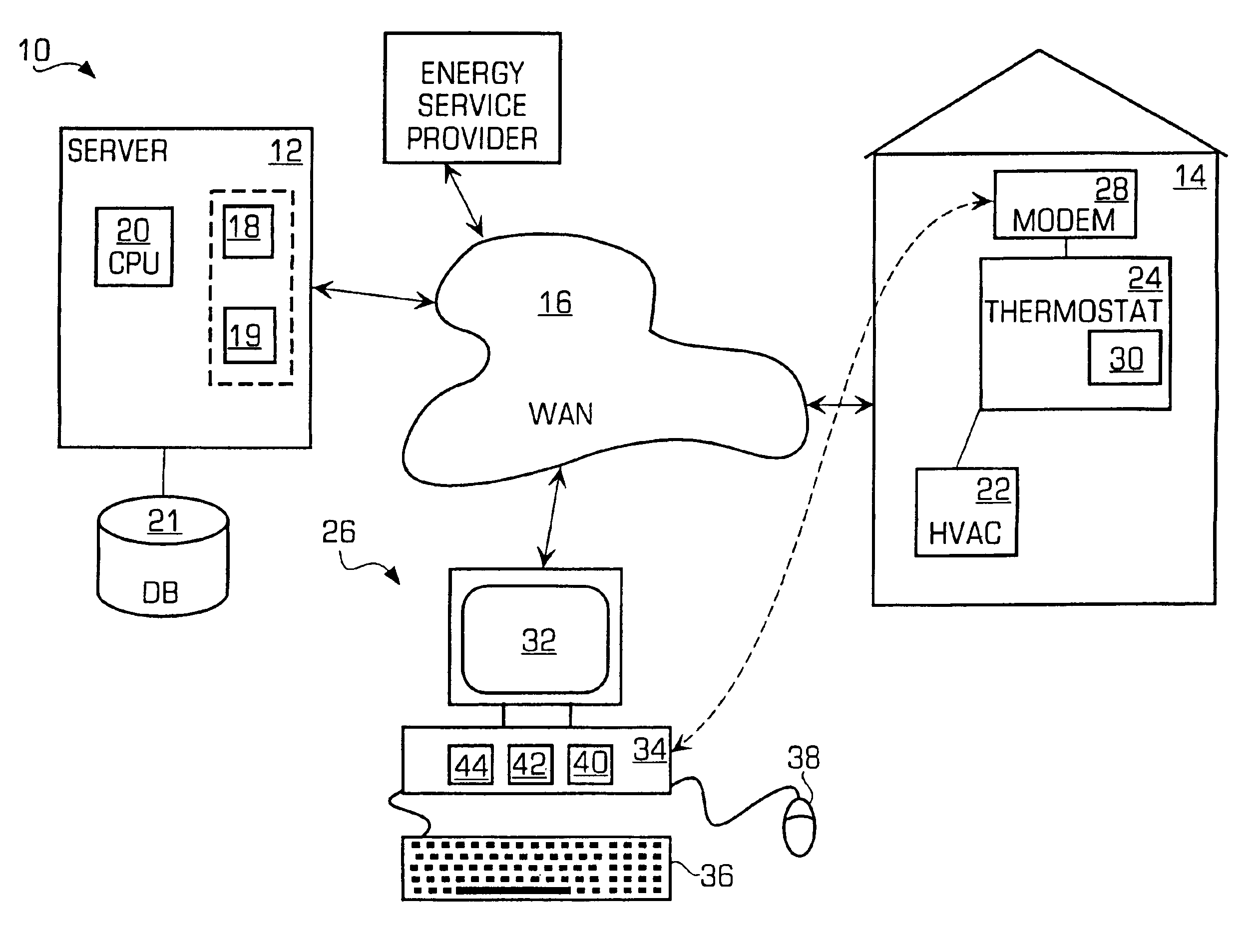
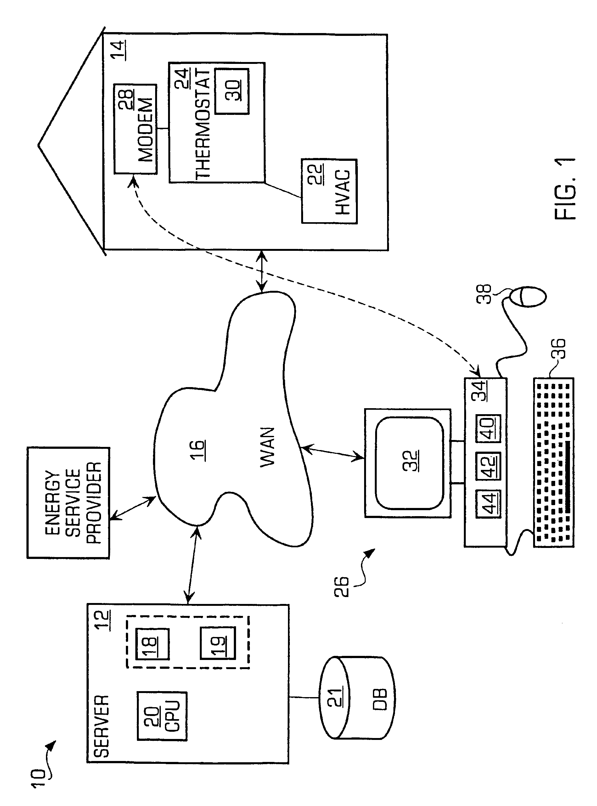
FIG. 1 is a diagram illustrating a load curtailment system 10 in accordance with the invention. As shown, the load curtailment system 10 may include a server 12 connected with one or more client nodes 14 across a data network 16, such as a wide area network (WAN) 16. In a preferred embodiment, the data network may be the Internet, or more particularly, the World Wide Web. It should be noted that while the invention is described as being provided over the World Wide Web, it may also be provided over a local area network, such as an intranet, and other network structures.

The server 12 may include a first software application 18 for performing energy management functions within the network, and a second software application 19 for allowing the remote control of thermostat devices 24 at a client node 14 both of which may be executed by a CPU 20. The software applications 18, 19 will be described in more detail below. A database 21 may be associated with the server 12 for storing curtail...


PUM

PropertyMeasurementUnit
energy usageaaaaaaaaaa
energyaaaaaaaaaa
offset temperatureaaaaaaaaaa

Abstract

A system and method are disclosed for performing energy usage management within a network. The system may include an energy management system, such as a thermostat device, that may be associated with an energy consuming entity, such as a residence. A server may be remotely located from the energy consuming entity and may perform one or more energy curtailment management operations within the network. The server may be in communication with the energy management system over the network. One or more software applications may be stored thereon for remotely controlling the energy management system in accordance with a particular energy curtailment management operation. Additionally, a database may be associated with the server for storing curtailment event information relating to the network. A signal may be transmitted by the server to the thermostat device to alter an offset temperature setting of the thermostat device thereby remotely controlling the operation of the thermostat device. The thermostat device may also include a networking software application for enabling the remote monitoring and controlling of the thermostat device.

Description

The present invention is related to a system and method for managing the use of energy.BACKGROUND OF THE INVENTIONEnergy management and energy cost management has always been an issue for many residents because of the increasing cost of energy. It is desirable to manage and analyze the energy consumption of a residence in order to reduce the total energy costs of the residence.With a conventional energy management approach, a residence may manage its own energy. However, due to conventional energy management devices, such as thermostats and the like, it can be difficult for a residence to efficiently and effectively manage energy usage on its own. Unfortunately, conventional thermostat systems, while capable of maintaining a desired temperature in the residence, are not generally precise in maintaining a particular temperature and thus fluctuate through a temperature range. This fluctuation can result in varying energy consumption, and variable energy cost, just to maintain a partic...

Claims


Application Information

Patent Timeline
Patent Type & Authority Patents(United States)
IPC IPC(8): F24D10/00G05D23/19
CPCG05D23/1905F24D10/00Y02B30/17
Inventor SCHURR, ALLAN J.YEE, GAYMOND
Owner ITRON
Why Eureka
Try Eureka